JAJSE38G November 2017 – December 2024 TCAN1043-Q1 , TCAN1043G-Q1 , TCAN1043H-Q1 , TCAN1043HG-Q1
PRODUCTION DATA
- 1
- 1 特長
- 2 アプリケーション
- 3 概要
- 4 Device Comparison Table
- 5 Pin Configuration and Functions
- 6 Specifications
- 7 Parameter Measurement Information
-
8 Detailed Description
- 8.1 Overview
- 8.2 Functional Block Diagram
- 8.3 Feature Description
- 8.4 Device Functional Modes
- 9 Application Information Disclaimer
- 10Device and Documentation Support
- 11Revision History
- 12Mechanical, Packaging, and Orderable Information
パッケージ・オプション
デバイスごとのパッケージ図は、PDF版データシートをご参照ください。
メカニカル・データ(パッケージ|ピン)
- D|14
- DMT|14
サーマルパッド・メカニカル・データ
発注情報
8.4.1 CAN Bus States
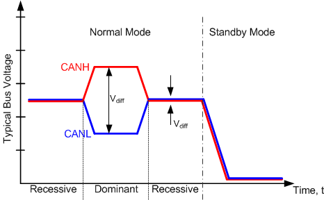
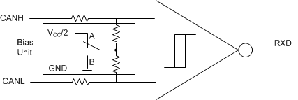
The CAN bus has two logical states during operation: recessive and dominant. See Figure 8-2 and Figure 8-3.
In the recessive bus state the bus is biased to a common mode of approximately VCC/2 (2.5V) via the high resistance internal input resistors of the receiver of each node on the bus. Recessive is equivalent to a logic high and is typically a differential voltage on the bus of approximately 0V.
The dominant bus state is when the bus is driven differentially by one or more drivers. Current flows through the termination resistors and generates a differential voltage on the bus. Dominant is equivalent to a logic low and is a differential voltage on the bus greater than the minimum threshold for a CAN dominant. A dominant state overwrites the recessive state.
During arbitration, multiple CAN nodes may transmit a dominant bit at the same time. In this case, the differential voltage of the bus is greater than the differential voltage of a single driver.
The host microprocessor of the CAN node uses the TXD terminal to drive the bus and receives data from the bus on the RXD terminal.
The TCAN1043xx-Q1 transceivers has a third bus state in low power standby mode where the bus terminals are weakly biased to ground via the high resistance internal resistors of the receiver. See Figure 8-2 and Figure 8-3.
 Figure 8-2 Bus States (Physical Bit Representation)
