JAJSJN8C January 2016 – August 2020 TPD3S714-Q1
PRODUCTION DATA
- 1 特長
- 2 アプリケーション
- 3 概要
- 4 Revision History
- 5 Pin Configuration and Functions
- 6 Specifications
- 7 Parameter Measurement Information
-
8 Detailed Description
- 8.1 Overview
- 8.2 Functional Block Diagram
- 8.3
Feature Description
- 8.3.1 AEC-Q100 Qualified
- 8.3.2 Short-to-Battery and Short-to-Ground Protection on VBUS_CON
- 8.3.3 Short-to-Battery and Short-to-VBUS Protection on VD+, VD–
- 8.3.4 ESD Protection on VBUS_CON, VD+, VD–
- 8.3.5 Low RON nFET VBUS Switch
- 8.3.6 High Speed Data Switches
- 8.3.7 Hiccup Current Limit
- 8.3.8 Fast Overvoltage Response Time
- 8.3.9 Integrated Input Enable
- 8.3.10 Fault Output Signal
- 8.3.11 Thermal Shutdown Feature
- 8.3.12 16-pin SSOP Package
- 8.4 Device Functional Modes
- 9 Application and Implementation
- 10Power Supply Recommendations
- 11Layout
- 12Device and Documentation Support
- 13Mechanical, Packaging, and Orderable Information
3 概要
TPD3S714-Q1 は、車載用 USB ハブ、ヘッド・ユニット、リア・シート用エンターテインメント、テレマティクス、メディア・インターフェイス・アプリケーションにおける USB コネクタの VBUS およびデータ・ラインのバッテリ短絡、短絡、ESD 保護のためのシングルチップ・ソリューションです。この統合型データ・スイッチは、USB のバッテリ短絡イベント中も最小限の信号劣化でクラス最高の帯域幅を提供します。1GHz という広い帯域幅により、車載 USB 環境で一般的な長いキャプティブ・ケーブルでも USB 2.0 ハイスピード (480Mbps) のクリーンなアイ・ダイアグラムを得ることができます。
バッテリへの短絡保護機能は、VBUS_CON、VD+、VD– ピンのすべての過電圧条件から内部システム回路を保護します。これらのピンのホットプラグおよび DC イベントのために、TPD3S714-Q1 は最大 18V の過電圧に対応できます。過電圧保護回路は業界でも最も信頼性の高いバッテリ短絡絶縁を行い、スイッチをシャットオフして、危険な電圧や電流スパイクから上流のトランシーバを保護します。VBUS_CON ピンは、最大 0.5A の高精度電流制限付きロード・スイッチにも使用できます。過電流保護回路は、グランドへの短絡中にアップストリーム・レールがドループしないように、電流を自動的に制限します。またこのデバイスは、VBUS_CON、VD+、VD– ピンにシステム・レベルの IEC 61000-4-2 および ISO 10605 ESD 保護を組み込んでいるため、外付けの高耐圧低容量 ESD ダイオードは不要です。
| 型番 | パッケージ | 本体サイズ(公称) |
|---|---|---|
| TPD3S714-Q1 | SSOP (16) | 4.90mm×3.90mm |
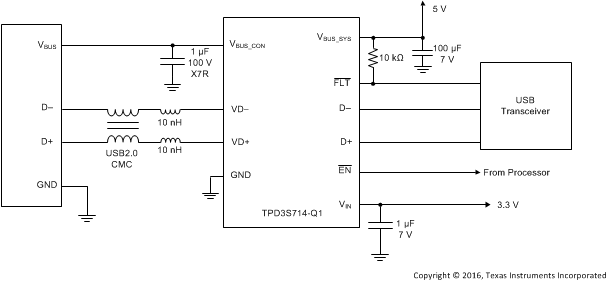
 代表的なアプリケーション回路図