SBAA632 April 2024 TMAG3001 , TMAG5170 , TMAG5170-Q1 , TMAG5170D-Q1 , TMAG5173-Q1 , TMAG5273
1 Introduction
Many critical functions in automotive vehicle systems including anti-lock braking systems (ABS), odometer, speedometer, and traction control rely on measuring the rotation speed of each wheel. Similarly in e-bikes this function is necessary not only to measure the traveling speed of the bicycle, but it is necessary to monitor the speed of rotation in the pedal crankset. This data is not only useful for fitness training computers that calculate a rider's energy output, but the data also provides confirmation that the rider is actively pedaling. This signal is required before the microcontroller enables motor output and is also used to set the motor speed based on programmed rider assist settings.
In many cadence monitor systems, this function has been implemented by placing a disc with several embedded magnets onto the pedal crankset. An example using 12 magnets is shown in Figure 1-1. With the magnets installed with alternating polarity, a 2D magnetic latch such as TMAG5110 can be used to track the passage of each magnet and provide a series of pulses as the magnet rotates.
 Figure 1-1 Discrete Magnet Cadence
Monitor
Figure 1-1 Discrete Magnet Cadence
MonitorWhen configured with a 2D latch, each pair of magnets can potentially create up to 4 transition states, for 24 total states per revolution in the pictured example. Alternatively, a single 1D latch can detect only 12 states - One for each magnet pole. If designed to achieve a 50% duty cycle, each state can represent about 15deg of rotation. While this is a relatively small amount of rotation, this can be challenging for the rider in cases where a heavier bike is stopped facing uphill. Additionally, the cost of the magnets and installation difficulty make this design less desirable.
Another possibility when using a bottom bracket mounted motor is to move the cadence detection interior to the motor. In these assemblies the pedals are connected to the motor output through a clutch. The clutch is disengaged until the rider pedals forward, and this protects the rider from injury that can occur by forcing the pedals to spin with the motor. In this system, it is possible to move the cadence sensor interior to the motor assembly using optical sensors. Even in this case, however, there is still potential for dirt and grease from the motor operation to contaminate the sensor over time.
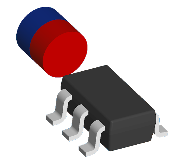
Whether designed into the system, or connected as an external module, back-biased magnetic sensors can be used to provide this function with greater resolution than the traditional design and free from concern caused by optical contaminants. In a back-biased configuration, the magnet remains fixed in a stationary position relative to the magnetic sensor as shown in Figure 1-2.
 Figure 1-2 Back-Bias
Configuration
Figure 1-2 Back-Bias
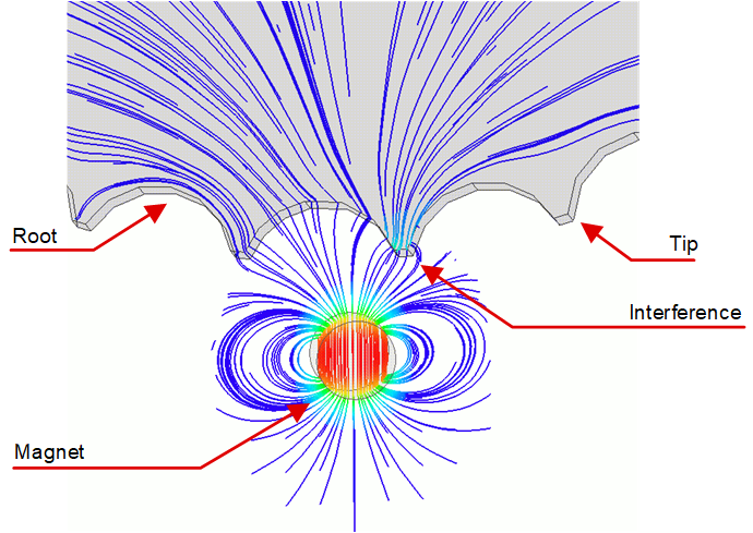
ConfigurationThe resulting field from the permanent magnet is then free to interact with the surroundings. When placed near a ferromagnetic gear or reluctance plate, the field from the stationary magnet can be drawn into the teeth of the gear. Since the range to the magnet changes as each tip and root of the gear teeth pass by, the strength of the magnetic flux density at the sensor can oscillate along multiple axes. Such an interaction is shown in the simulated field behavior depicted in Figure 1-3. Here, the field is distorted towards the nearby sprocket tooth to the right of the magnet.
 Figure 1-3 Magnetic Field
Interaction