SBAA635 July 2024 AFE7950 , AFE7950-SP , AFE7951 , AFE7953 , AFE7954 , AFE7955
1 Introduction
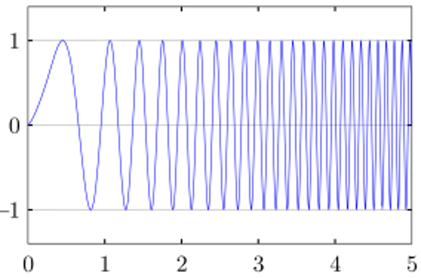
A chirp is a signal in which the frequency increases (up-chirp) or decreases (down-chirp) with time. In some sources, the term chirp is used interchangeably with sweep signal. Chirp is commonly applied to sonar, radar, and laser systems, and to other applications, such as in spread spectrum communications. A linear chirp waveform is also referred to as Linear Frequency Modulation (LFM) Waveform.
 Figure 1-1 A Linear Chirp Waveform (A
Sinusoidal Waveform that Increases in Frequency Linearly in Time)
Figure 1-1 A Linear Chirp Waveform (A
Sinusoidal Waveform that Increases in Frequency Linearly in Time)One popular application of this is Linear frequency modulation (LFM) based jamming, also known as chirp jamming, is a technique used to disrupt communication systems that rely on linear frequency modulation for transmission. In LFM-based jamming, the jammer emits a signal that continuously varies in frequency over time according to a linear function. This results in a signal with a continuously changing frequency, resembling a chirp in the frequency domain. When the jammer's chirp signal overlaps with the frequency range used by the target communication system, it interferes with the reception of the legitimate signal. This interference can disrupt the communication link, causing errors in data transmission, loss of synchronization, or complete loss of communication. LFM-based jamming is effective against communication systems that are not designed to handle or mitigate frequency-modulated interference. However, some modern communication systems employ techniques such as frequency agile modulation or advanced signal processing to mitigate the effects of LFM-based jamming.
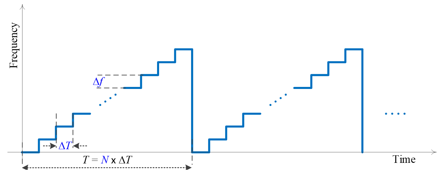
Figure 1-2 shows an example of stepped LFM frequency versus time profile.
 Figure 1-2 LFM Frequency versus Time
Profile
Figure 1-2 LFM Frequency versus Time
ProfileHere,
Δf is the frequency step
Δt is the dwell time, that is, the time for which one of the frequencies is transmitted.
T = N × ΔT is the total sweep time.