SBAU382A November 2021 – January 2022 ADS7029-Q1 , ADS7039-Q1 , ADS7040 , ADS7041 , ADS7042 , ADS7043 , ADS7044 , ADS7046 , ADS7047 , ADS7049-Q1 , ADS7052 , ADS7054 , ADS7056 , ADS7057
4.2 EVM GUI Global Settings for ADC Control
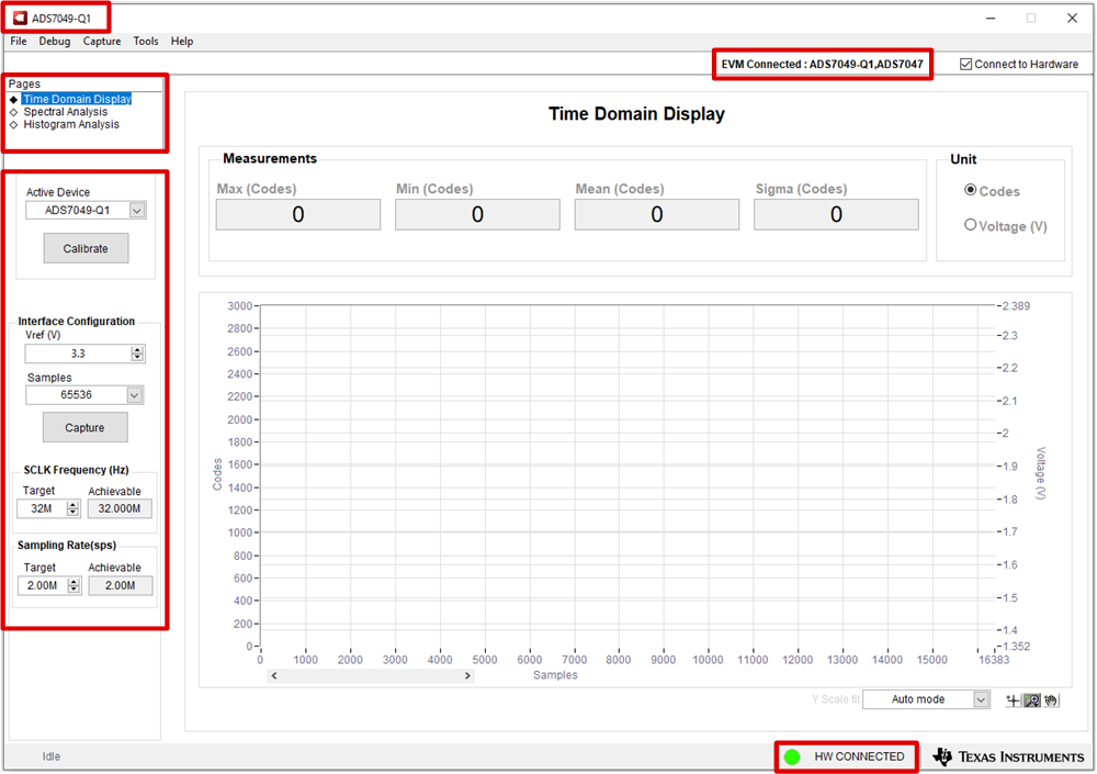
Figure 4-2 shows the default screen when the GUI is started. The GUI defaults to the Time Domain Display, though other options are available in the Pages control box. When the GUI connects successfully, HW Connected shows in green in the bottom ribbon and the specific devices included on the EVM are identified in the upper right. In this case, ADS7049-Q1 and ADS7047 are included on the EVM represented by Figure 4-2.
 Figure 4-2 ADS704X-5XEVM GUI
Overview
Figure 4-2 ADS704X-5XEVM GUI
OverviewThe EVM global controls are located on the left-hand side of the GUI and are as follows:
- Active Device (also shown in the upper left corner of the GUI)
- VREF (only valid if AVDD is modified from the default value as per Section 2.2, otherwise leave this value set to 3.3 V)
- Samples
- SCLK Frequency
- Sampling Rate