SBAU412A November 2022 – May 2024 AFE7900 , AFE7903 , AFE7906 , AFE7920 , AFE7921 , AFE7950
- 1
- Abstract
- Trademarks
- 1 Introduction
- 2 Prerequisites
- 3 Typical Bare-Metal Design Flow
- 4 Background
- 5 Add Microblaze and SPI IP for Use in Vitis for Embedded Development
- 6 Create New Platforms in Vitis
- 7 Create New Application Projects in Vitis
- 8 Build Application Projects
- 9 Generate SPI Log for AFE79xx EVM
- 10AFE79xxEVM Board Modifications
- 11Configure the AXI GPIO
- 12Configure the AXI SPI
- 13Set Up and Power on Hardware
- 14Set up ZCU102 Board Interface for VADJ_FMC
- 15Debug Application Projects and Set up Vitis Serial Terminal
- 16Execute the Application
- 17Revision History
10 AFE79xxEVM Board Modifications
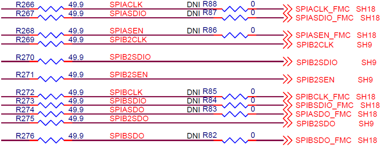
To connect AFE SPI to the FPGA, the modifications below must be made:
- Remove R266, R267, R268, and R274 (Found on the bottom of the EVM).
- Install 0Ω resistors for R88, R87, R86, and R83 (Found on the top of the EVM).

The LMK SPI has no connection to the FMC connector, so for the FPGA to control the LMK SPI the following board modifications must be made.
- Connect LMK_SCK to SPIACLK (Wire from R88 to R248).
- Connect LMK_SDIO to SPIASDIO (Wire from R87 to R249).
- Connect LMK_CS to pin D26 of the
of the FMC connector.
- To do this a wire can be connected from R242 to the open pad of R9 that is connected to the FMC.