SBOA575 September 2023 INA823 , OPA2387 , XTR115 , XTR116
5 Verification and Measured Performance
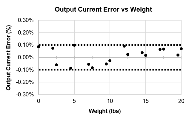
The measured output current versus weight is shown in Figure 5-1. The measured results are compared with the simulated and calculated values in Table 5-2. The measured results are ±0.1% accurate as shown in Figure 5-2. The experimentation setup with the load cell is detailed in the Appendix 1: Load Cell and Experimentation Setup. The total current consumption is calculated in Equation 14.
Equation 14.
Table 5-1 Design Goal vs Calculated, Simulated, and
Measured Performance
| Weight | Goal | Calculated | Simulated | Measured | |
|---|---|---|---|---|---|
| Iout (Min) | 0 lbs | 4 mA | 4.0959 mA | 4.0963 mA | 4.0994 mA |
| Iout (Max) | 20 lbs | 20 mA | 20.1404 mA | 20.1397 mA | 20.1545 mA |
 Figure 5-1 Measured Output Current vs
Weight Transfer Function
 Figure 5-2 Output Current Error vs
Weight