SBOA603 June 2024 INA700 , INA740A , INA740B , INA745A , INA745B , INA780A , INA780B
1 Introduction
Current sense amplifiers help measure the differential voltage across a shunt resistor and amplify this value to provide a single-ended output voltage. This output voltage is then measured by an external ADC and a Microcontroller to calculate the current present on each rail. Meanwhile, a Digital power monitor helps measure this voltage and performs mathematical processing on-chip with the use of a built-in ADC, freeing up system processors to handle separate tasks. This helps enable higher bit-depth with the digital power monitor providing additional features such as an alert functionality, energy, power, current, voltage, and die temperature monitoring on certain devices. When designing a design to measure power, an external shunt resistor is designed in series using kelvin connections to measure a differential voltage across the shunt.
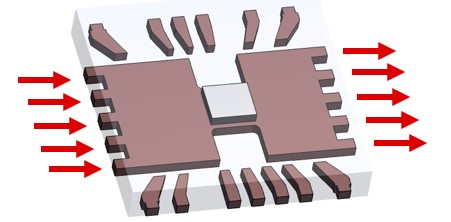
 Figure 1-1 EZShunt™ Leadframe
This input is then processed to be a single-ended digital output by the device. On the contrary, EZShunt™ technology eliminates the need for an external shunt resistor, or ADC while measuring multi-modal values since the lead frame functions as the shunt resistor as shown in Figure 1-1.
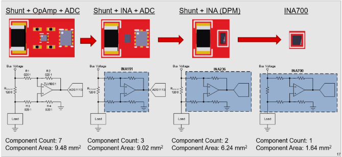
 Figure 1-2 Current Sense Design Variations in Size and
Component Count
Figure 1-2 Current Sense Design Variations in Size and
Component CountIn comparison to alternative current sensing designs using a shunt, opamp, current sense amplifier, or digital power monitor, we can see the footprint and component count reduction EZShunt™ technology offers using Figure 1-2. Reduction in component count and footprint also offers a cost-optimized path toward sensing power, current, voltage, energy while maintaining highly precise accuracies.
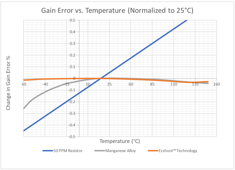
In accordance with design size, total design accuracy is a crucial component in analyzing the effectiveness of each variant. Since the EZShunt™ leadframe is composed of copper, there is a tendency for the leadframe to drift according to temperature. However, TI technology leverages active calibration techniques that compensate for lead frame drift and variation in error based on temperature utilizing the capabilities of monitoring die temperature as shown by the typical behavior in Figure 1-3.
 Figure 1-3 Gain Error vs. Temperature
(Normalized to 25°C)
Figure 1-3 Gain Error vs. Temperature
(Normalized to 25°C)This form of compensation alongside precise measurement procedures allows for an all-in-one device providing telemetry requirements for any application. In accordance with the benefits, analyzing factors that culminate to form errors allows us to visualize the true accuracies and error comparisons between traditional external shunt and integrated current sensing designs. Data sheets and errors specified for traditional Current sense amplifiers and Digital power monitors do not include the additional error produced by an external shunt. This error is often considered by the end user and defined according to the ambient field temperature depending on the total design. Meanwhile, accuracies and parameters defined by our EZShunt™ products include all errors associated with the integrated shunt and are specified according to ambient field temperature as well.