SCEA147 September 2024 TXB0104 , TXB0302 , TXB0304
3.2.1 Bench Setup and Results
To highlight the impact of the series dampening resistor, multiple resistor values were used for impedance matching with the TXB0304, then compared to the TXB0104 and competitor part. A second setup is also provided to replicate different transmission line characteristics.
 Figure 3-6 Impedance Matching Bench Setup
Note that not any series resistor can work and improve output conditions. System designers may need to test with different values that deem fit and compatible with the system requirements. The following example waveforms show the behavior of improper matching of TXB0304 to a transmission line. This is clear that both cases with 33Ω and 56Ω show reflections throughout the signal with no improvements.
 Figure 3-7 Output of the Unmatched TXB0304 (33Ω and 56Ω), TXB0104 (0Ω) , Competitor (0Ω)
 Figure 3-8 Output of the Matched TXB0304 (43Ω), TXB0104 (0Ω) , Competitor (0Ω)
- Once matched, TXB0304 observed designed for
performance compared to other devices
- Similar output characteristics to the TXB0104.
- Less overshoot or undershoot than competitor device.
- See device data sheets for acceptable lumped sum capacitance and data rates.
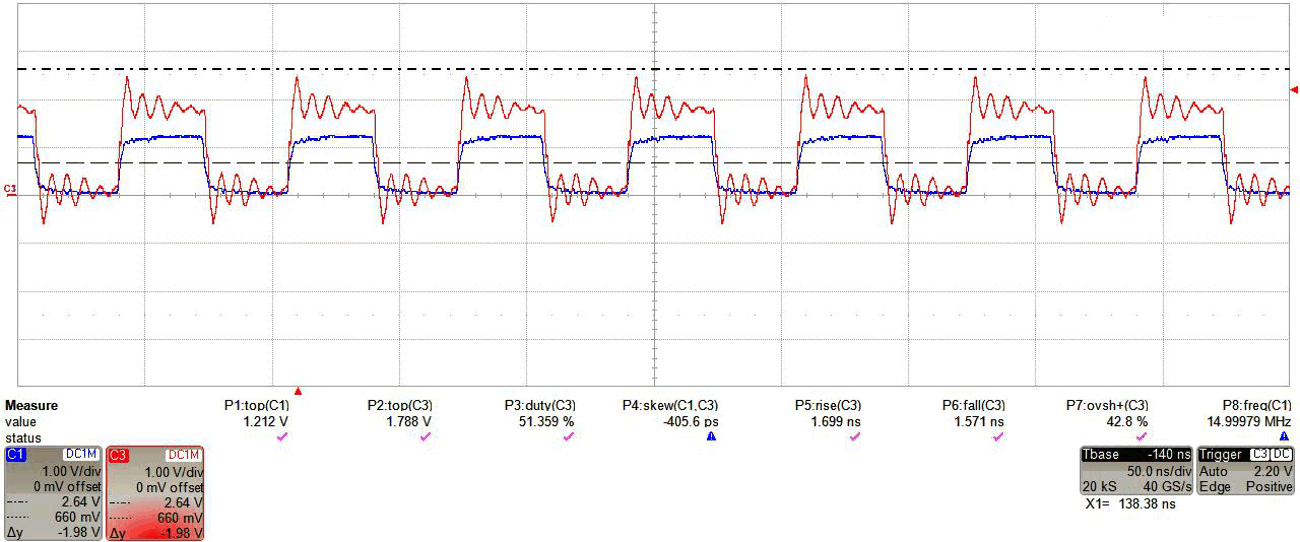
In the second setup, the cabling was swapped to imitate a different output load to the TXB. This time, a 56Ω series resistor was used as the resistor matched closer to the transmission medium.
 Figure 3-9 Output of the Unmatched TXB0304 (Red) With 0Ω Given Input Signal (Blue)
 Figure 3-10 Output of the Matched TXB0304 (Red) With 56Ω Given Input Signal (Blue)
By using the 56Ω series resistor shown in Figure 3-10, oscillations become dampened and overshoot % decreased from 42.8% to 14.3%.
Note the two setups, Figure 3-8 and Figure 3-10 were benched with different cabling at the output of the TXB0304. In each case, the required series impedance value differed to effectively match the transmission line, which shows that trial and error might be needed to find the best match.