SLLA621A September 2023 – October 2023 MCF8315A , MCF8316A
2.2.1 Solve the Thermal Problem From Hardware
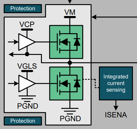
Since MCF831x devices are an integrated FET device, the conduction loss and turn-off loss of the Mosfet can inevitably affect the thermal performance. For most logarithm integrated FET motor control device, the Rds(ON) of HS+LS is 200moh approximately 300moh, but for MCF831x, Rds(ON) (HS+LS) is 95mohm, which can greatly reduce the conduction loss. And for MCF831x, the Rds(ON) of MOSFET lower bridge is used as the sampling resistor to further reduce the loss caused by the sampling resistor in the conventional drive.
 Figure 2-1 MCF831X Current Sensing Circuit
For the loss caused by the internal LDO and buck, view the power rail path inside the MCF831x from Figure 2-2.
From the perspective of efficiency, the best practice is to enable the internal buck or LDO, and set the Buck output to 3.3 V so that the loss caused by the LDO can reach the minimum value.
 Figure 2-2 MCF831X Power Sequence