SLOA277B january 2019 – july 2023 LM124 , LM124-N , LM124A , LM158 , LM158-N , LM158A , LM224 , LM224-N , LM224A , LM258 , LM258-N , LM258A , LM2902 , LM2902-N , LM2902-Q1 , LM2902K , LM2902KAV , LM2904 , LM2904-N , LM2904-Q1 , LM2904B , LM2904B-Q1 , LM2904BA , LM321 , LM324 , LM324-N , LM324A , LM358 , LM358-N , LM358A , LM358B , LM358BA , TS321 , TS321-Q1
5.2 Low VCC Output Range Supporting –40°C
The output range is typically 0.75 V to 1.5 V for a bidirectional load current of 100 µA at –40°C. This output range is just 25% of the supply voltage range. The output range can be increased to 0.1 V to 1.5 V with a bidirectional load current of 12 µA. If all loads terminate to ground, then the output range is 0 V to 1.4 V for a 1-mA load. The largest output range possible requires using an external pullup resistor. For example, using a 5-kΩ resistor gives a typical –40°C output range from 0.8 V to 2.7 V.
Lower resistance gives more design margin and a slightly higher, typical range. VOH improves with lower resistance, but VOL degrades and power consumption increases. The op amp does not oppose the pullup resistor other than the constant sink driver current that is always on. The high output level is limited by the pullup resistor, feedback, and other loads. The constant sink current driver reduces VOH as this current flows through the pullup resistor. All of the output ranges in this section are based on the typical VOH and VOL curves in this application note. Always add design margin when using typical data.
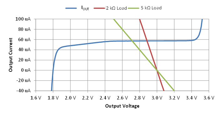
Figure 5-1 shows typical IOH vs VOH curves given Ta = 25°C and VCC = 3 V. The constant current sink driver from Figure 3-1 is responsible for this current flow. This current value can vary from device to device and across temperature. Do not pull up the output to a voltage higher than VCC unless an external diode to VCC is used to limit output voltage.
 Figure 5-1 Output Current vs Output Voltage for Pullup
Resistor Usage
Figure 5-1 Output Current vs Output Voltage for Pullup
Resistor UsageThe output VOH level is significantly increased by a pullup resistor that provides at least 100 µA. In Figure 5-1, output current vs output voltage was measured. Two pullup resistor load lines, 2 kΩ and 5 kΩ, are included on the chart. With no pullup resistor or any other load, the current is zero and VOH is 1.8 V. The 5-kΩ resistor load line intersects the output current curve at VOH = 2.73 V and the 2-kΩ load line intersects the output current curve at VOH = 2.88 V. If the output current were 100 µA, then VOH would be reduced to [2.8 V, 2.5 V] for the [2k , 5k] loads. Note that another advantage of unidirectional current or very low bidirectional current is the lack of time delay that occurs when switching between the NPN Darlington and PNP emitter follower drivers.
In this family of devices, TS321, LM358B, LM2904B, LM324B, and LM2902B typically have higher constant sink currents. Therefore, pulldown resistors are recommended instead of pullup resistors for these parts.