SLOA343 August 2024 TPS543820 , TPS543A22 , TPSM843620 , TPSM843A22
4 Test Results for Radiated Interference
The following data was taken in the CISPR Chamber with CISPR32 pre-compliant setup. These results are not officially CISPR certified. The table below shows a summary of the experimental setup for each set of tests. A photo of the setup is shown in Figure 4-1. The results show a significant improvement in the radiated emissions, showing that EMI can be heavily reduced by changing only the layout.
Table 4-1 Testing Conditions
| IC | Vin | Vout | Iout | Switching Frequency |
|---|---|---|---|---|
| TPS543820 | 12V | 1.2V | 8A | 500kHz |
| TPSM843620 | 12V | 1.2V | 6A | 500kHz |
| TPS543A22 | 12V | 1.2V | 10A | 500kHz |
| TPSM843A22 | 12V | 1.2V | 10A | 500kHz |
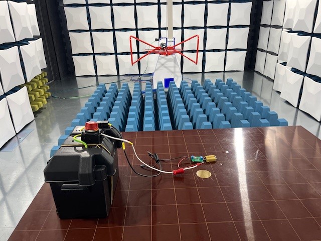 Figure 4-1 Radiated Emissions Testing Setup
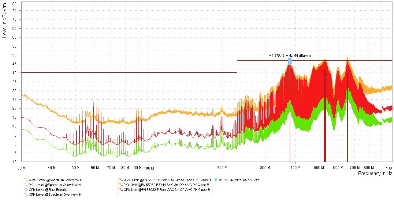 Figure 4-2 TPS543620 EVM Results
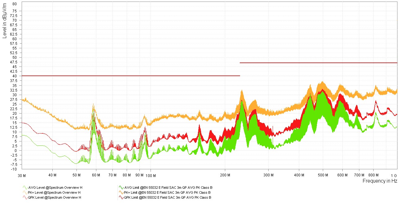 Figure 4-4 TPSM843620 EVM Results
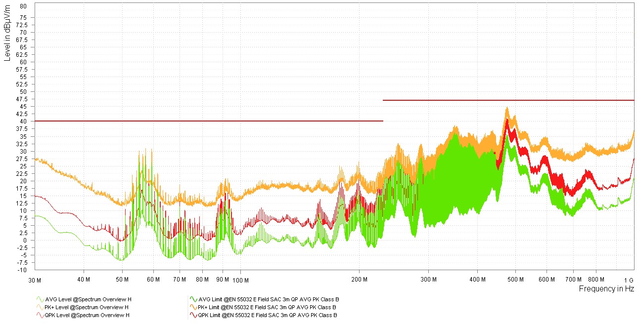 Figure 4-6 TPS543B22 EVM Results
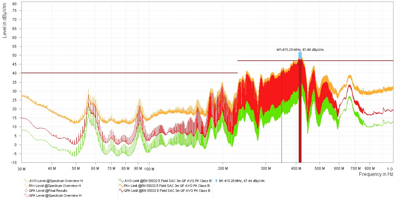 Figure 4-8 TPSM843B22 EVM Results
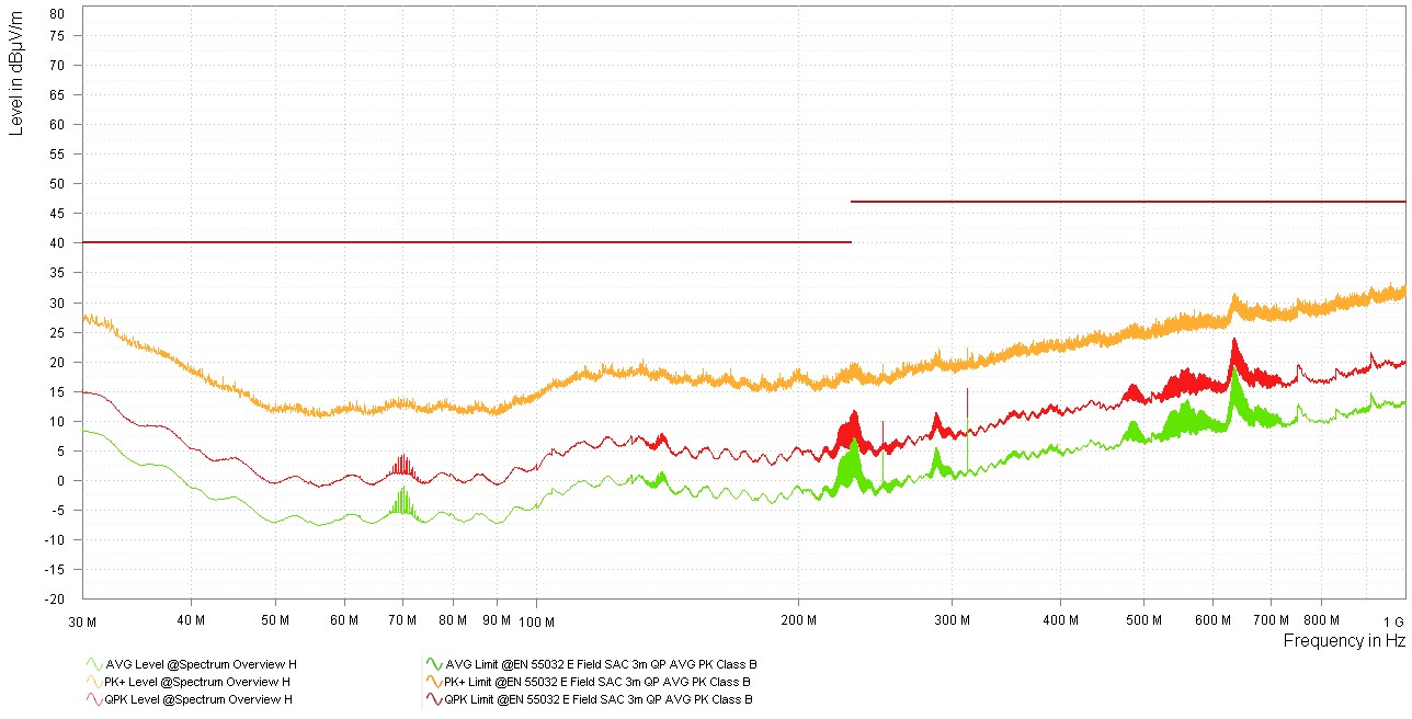 Figure 4-3 TPS543820 EMI-Optimized Results
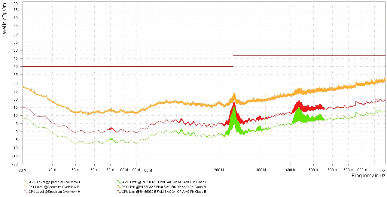 Figure 4-5 TPSM843620 EMI-Optimized Results
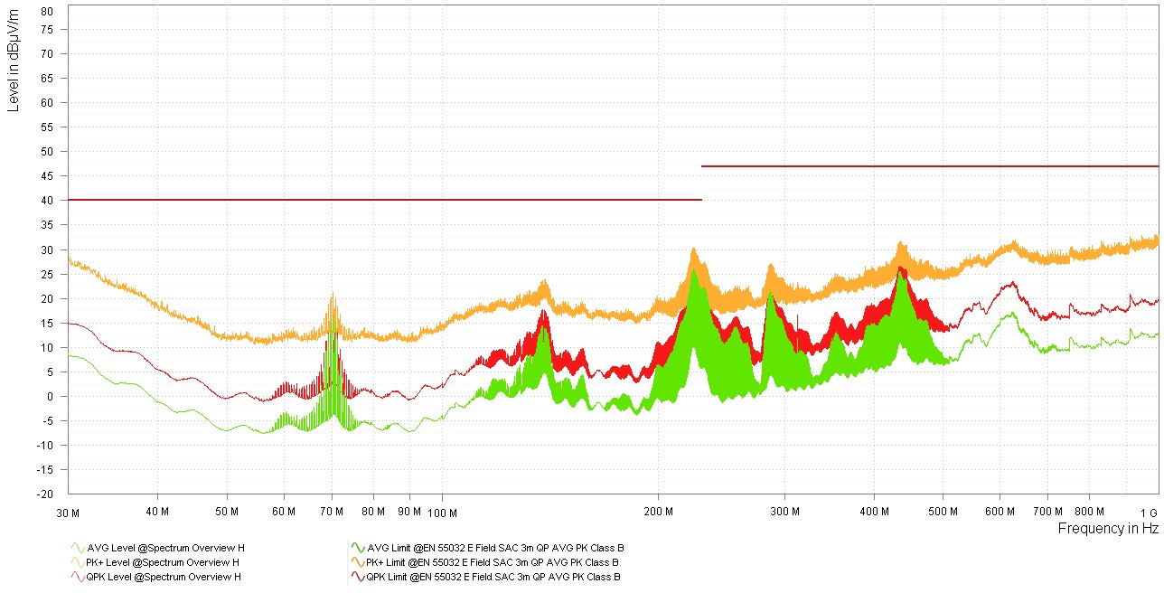 Figure 4-7 TPS543A22 EMI-Optimized Results
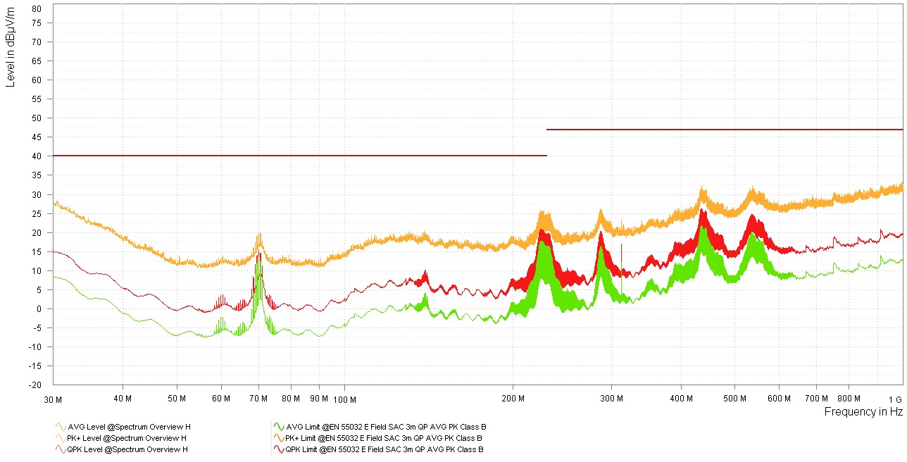 Figure 4-9 TPSM843A22 EMI-Optimized Results