SLOA343 August 2024 TPS543820 , TPS543A22 , TPSM843620 , TPSM843A22
5 EMI Filtering
To help reduce conducted EMI at the switching frequency of our boards, we tested the effects of two different input filter types:
- A ferrite bead-based pi filter
- An Inductor-based pi filter
The pi filter is shown in Figure 5-1, with the ferrite bead or inductor between two capacitors.
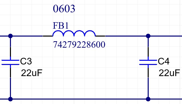 Figure 5-1 Example pi Filter With Ferrite
Bead
Figure 5-1 Example pi Filter With Ferrite
BeadSimulated bode plots for the ferrite bead pi filter are shown in (Figure 5-2) and inductor pi filter (Figure 5-3).
Figure 5-3 shows that the ferrite bead filter has the max attenuation occurring at just over 1MHz, after which the attenuation begins to flatten out, while the inductor filter similarly has the max attenuation occurring at just over 1MHz, after which the attenuation begins to flatten out.
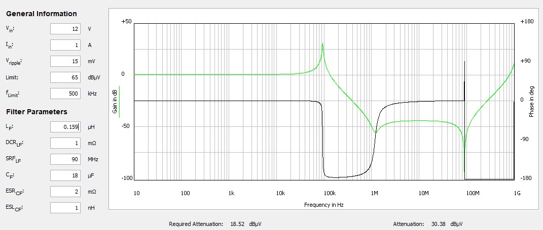 Figure 5-2 Bode Plot for Ferrite Bead
pi Filter
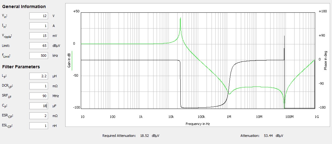 Figure 5-3 Bode Plot for Inductor pi
Filter
Figure 5-3 Bode Plot for Inductor pi
FilterWe tested the simulation results with a series of conducted emissions tests, with the test setup shown in Figure 5-4. In the following conducted EMI data, for the frequencies below 2MHz, the inductor filter caused significantly more improvement to the conducted EMI than the ferrite bead filter. At the switching frequency of 500khz, the 2.2uH inductor filter created 35dB more attenuation.
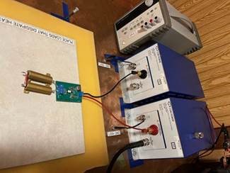 Figure 5-4 Conducted Emissions Test
Setup
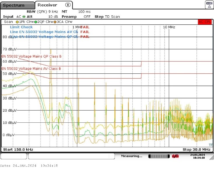 Figure 5-5 TPS543820 Conducted EMI
Results With Ferrite Bead Filter
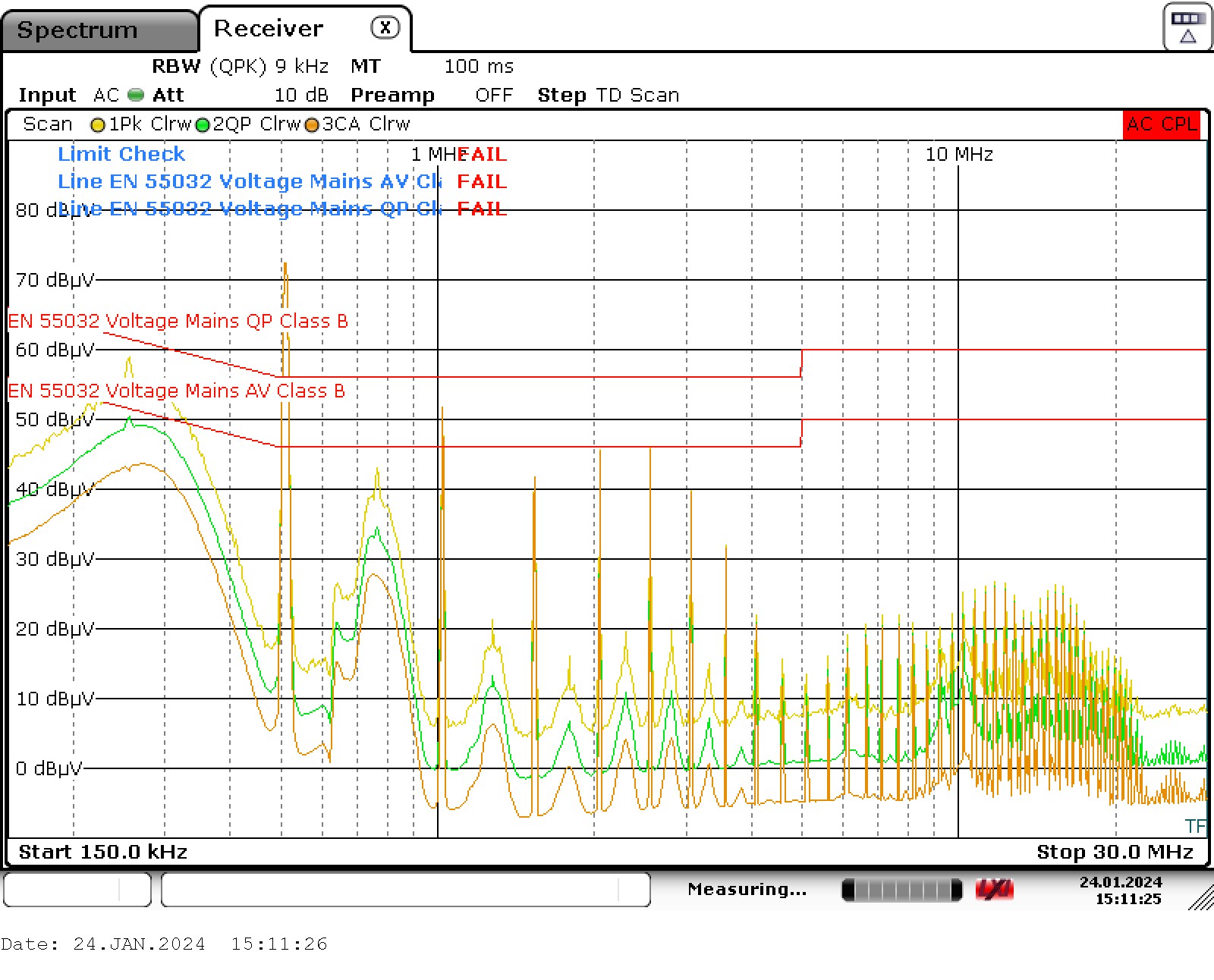 Figure 5-7 TPSM843620 Conducted EMI
Results With Ferrite Bead Filter
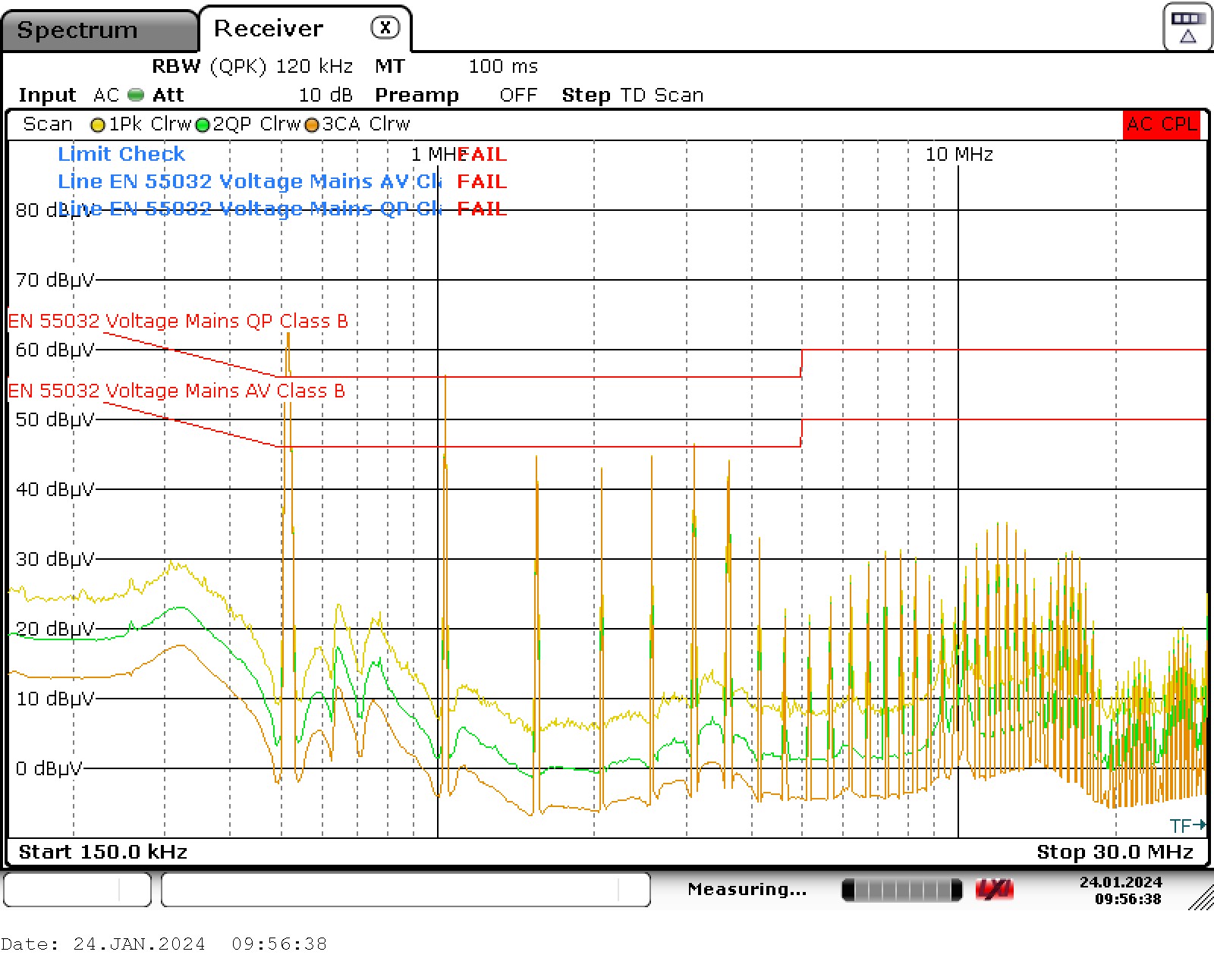 Figure 5-9 TPS543A22 Conducted EMI
Results With Ferrite Bead Filter
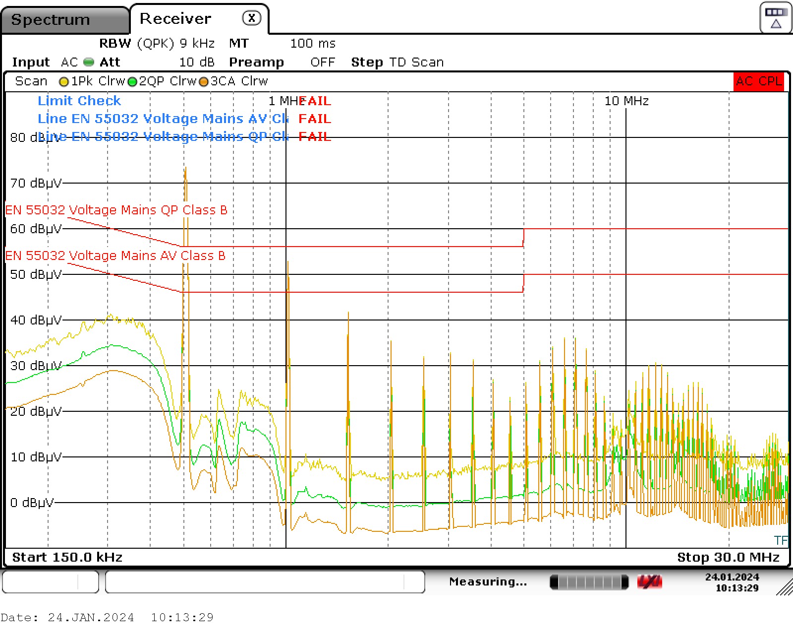 Figure 5-11 TPSM843A22 Conducted EMI
Results With Ferrite Bead Filter
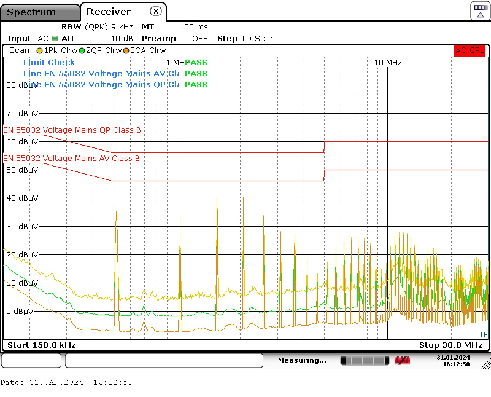 Figure 5-6 TPS543820 Conducted EMI
Results With Inductor Filter
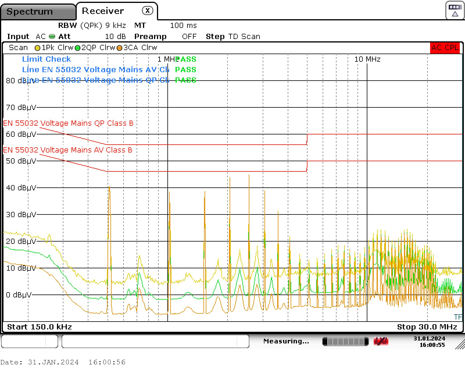 Figure 5-8 TPSM843620 Conducted EMI
Results With Inductor Filter
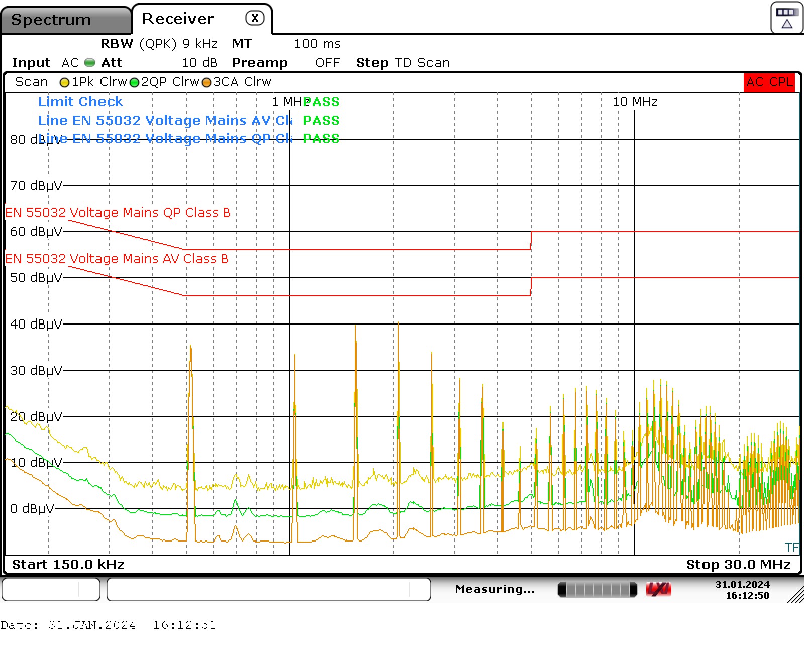 Figure 5-10 TPS543A22 Conducted EMI
Results With Inductor Filter
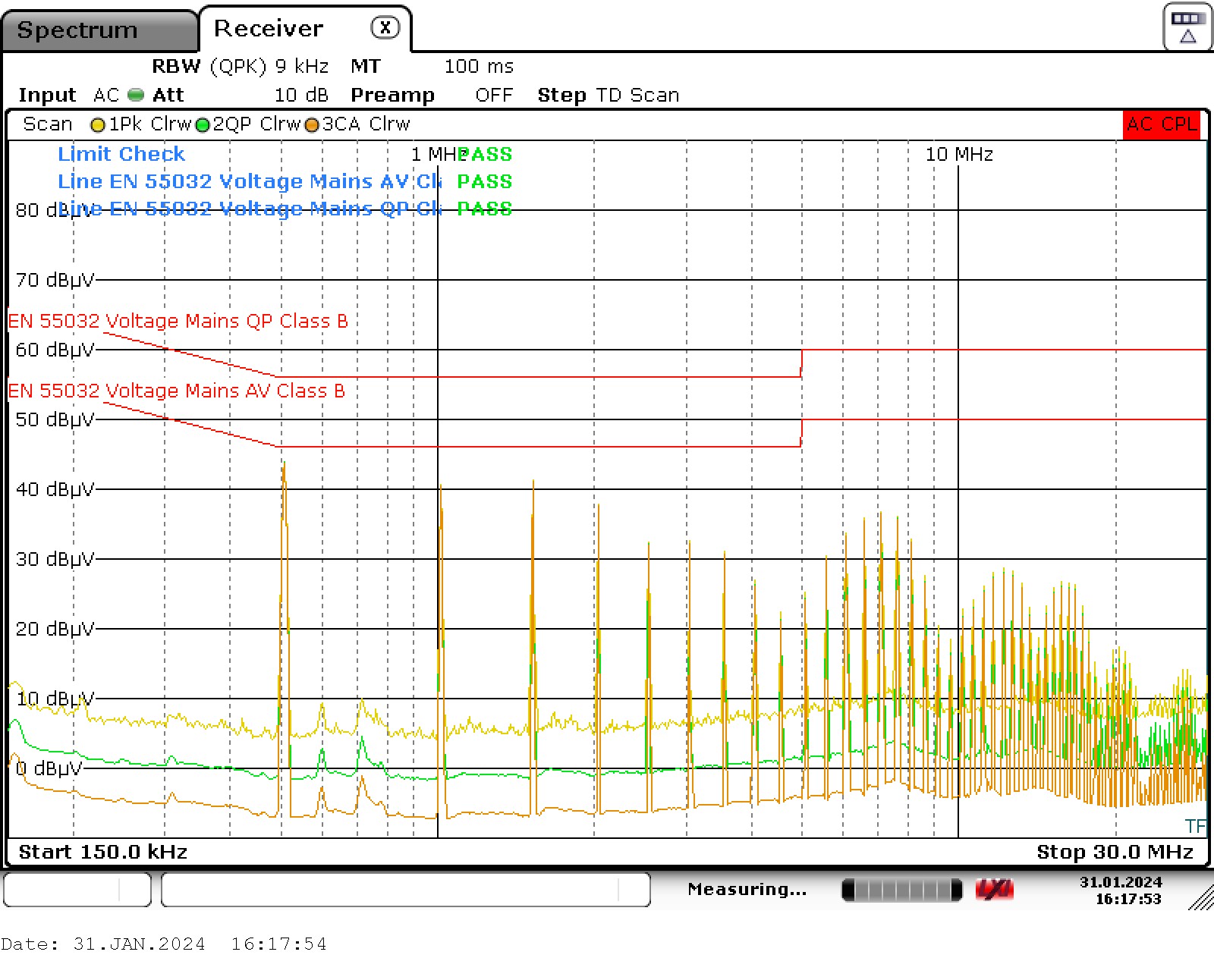 Figure 5-12 TPSM843A22 Conducted EMI
Results With Inductor Filter