SLOA343 August 2024 TPS543820 , TPS543A22 , TPSM843620 , TPSM843A22
3 Designing for EMI-Optimized Layout
Four different layouts are created for the four different buck regulators:
- TPS543820
- TPSM843620
- TPS543A22
- TPSM843A22
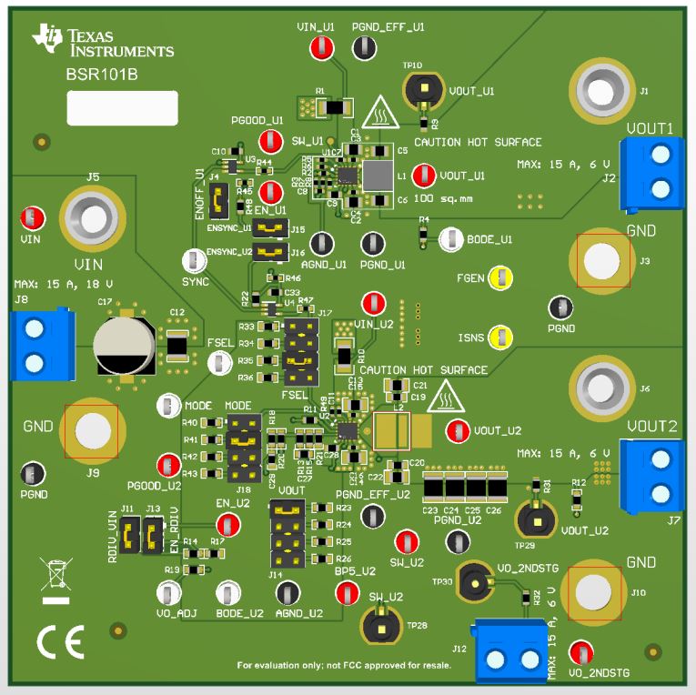 Figure 3-1 TPS543620 EVM Standard
Layout
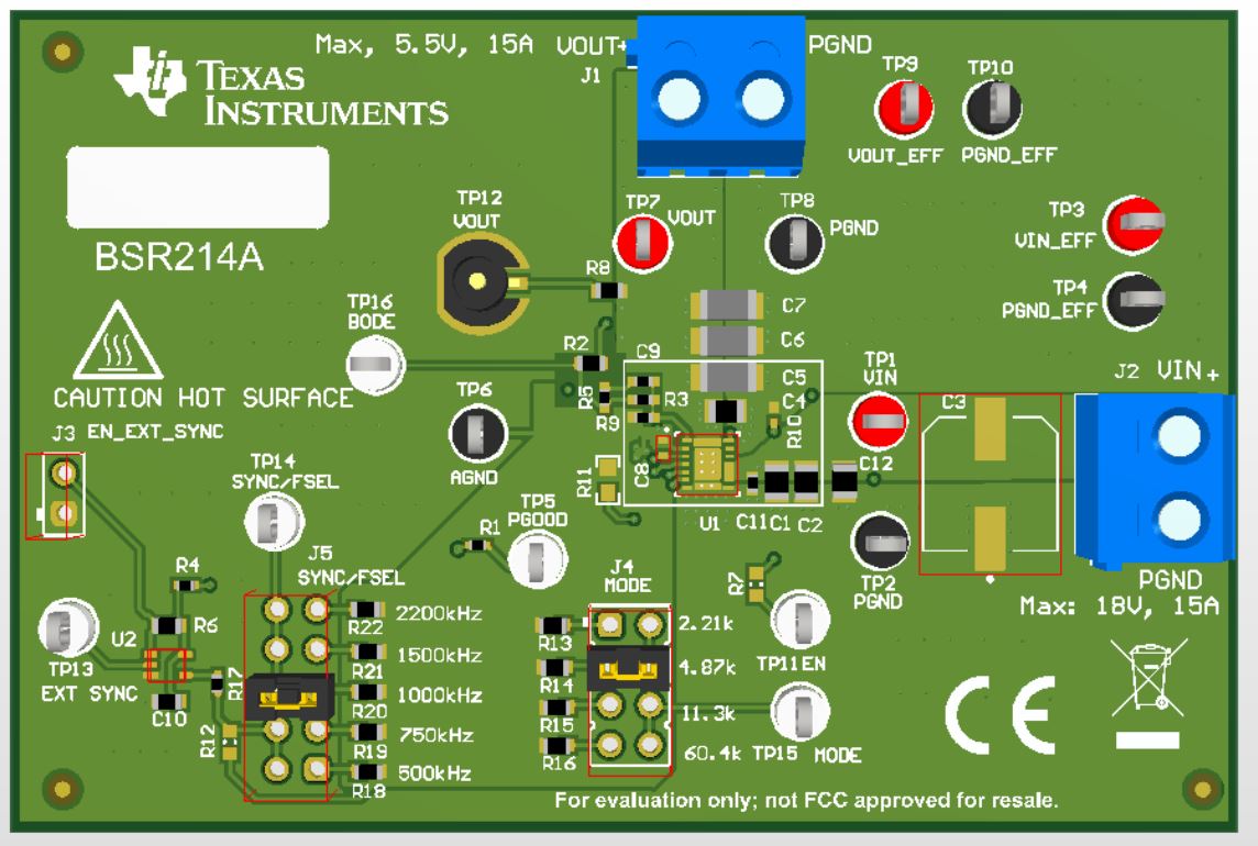 Figure 3-3 TPSM843620 EVM Standard
Layout
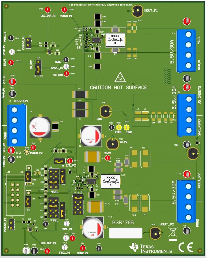 Figure 3-5 TPS543B22 EVM Standard
Layout
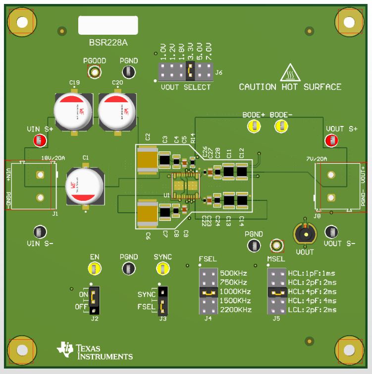 Figure 3-7 TPSM843B22 EVM Standard
Layout
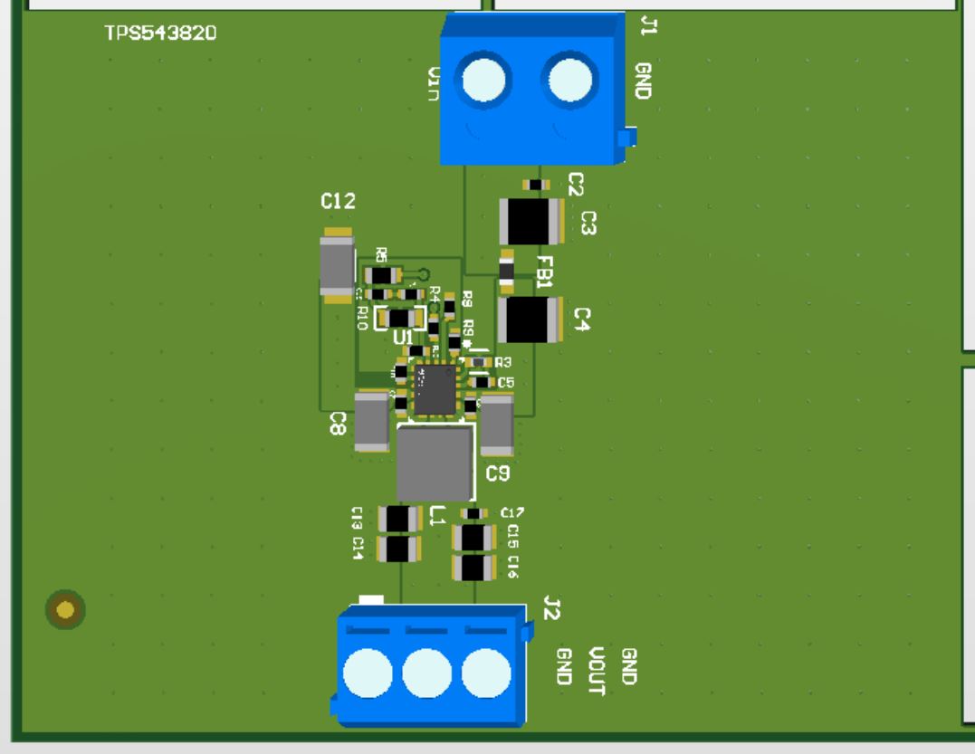 Figure 3-2 TPS543820 EMI-Optimized
Layout
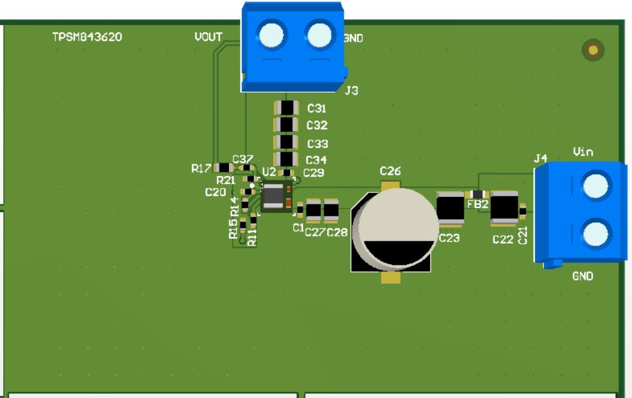 Figure 3-4 TPSM843620 EMI-Optimized
Layout
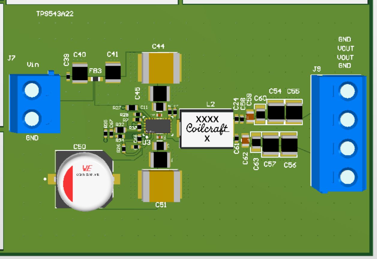 Figure 3-6 TPS543A22 EMI-Optimized
Layout
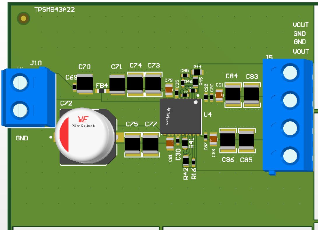 Figure 3-8 TPSM843A22 EMI-Optimized
Layout