SLUAAP2 March 2023 LMG2610 , UCC28782
- Abstract
- Trademarks
- 1Introduction
- 2A Brief Introduction to GaN's Value
- 3The Active Clamp Flyback
- 4The Value of GaN in Active Clamp Flyback
- 5Leveraging Integrated GaN to Simplify ACF Stage
- 6Physical Design Implementations Using LMG2610 Integrated Half-Bridge and UCC28782 ACF Controller
- 7Leverage Design Tools for ACF
- 8Summary
- 9References
6.1 UCC28782EVM-030
The first design is a 65-W USB-C PD adapter with the following specifications in Table 6-1.
| Application | USB-C PD Adapters |
|---|---|
| Input Voltage | 85 – 265 Vac |
| Output | 20 V/3.25 A, 15 V/3 A, 9 V/3 A, 5 V/3 A |
| Max. Power | 65 W |
The UCC28782EVM-030 is able to achieve a power density of or . The UCC28782EVM-030 compact form-factor is show in Figure 6-1.
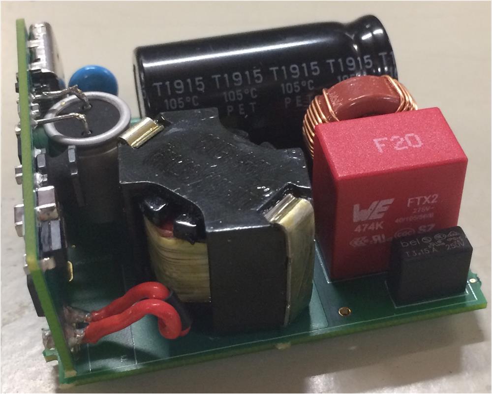 Figure 6-1 UCC28782EVM-030 in
High-Density Configuration
Figure 6-1 UCC28782EVM-030 in
High-Density ConfigurationThis small size is achieved by operating with a maximum switching frequency of approximately 240 kHz, which allows a smaller inductance requirement, and as a result, a smaller transformer core size.
The full load efficiency across input voltage is shown in Figure 6-2.
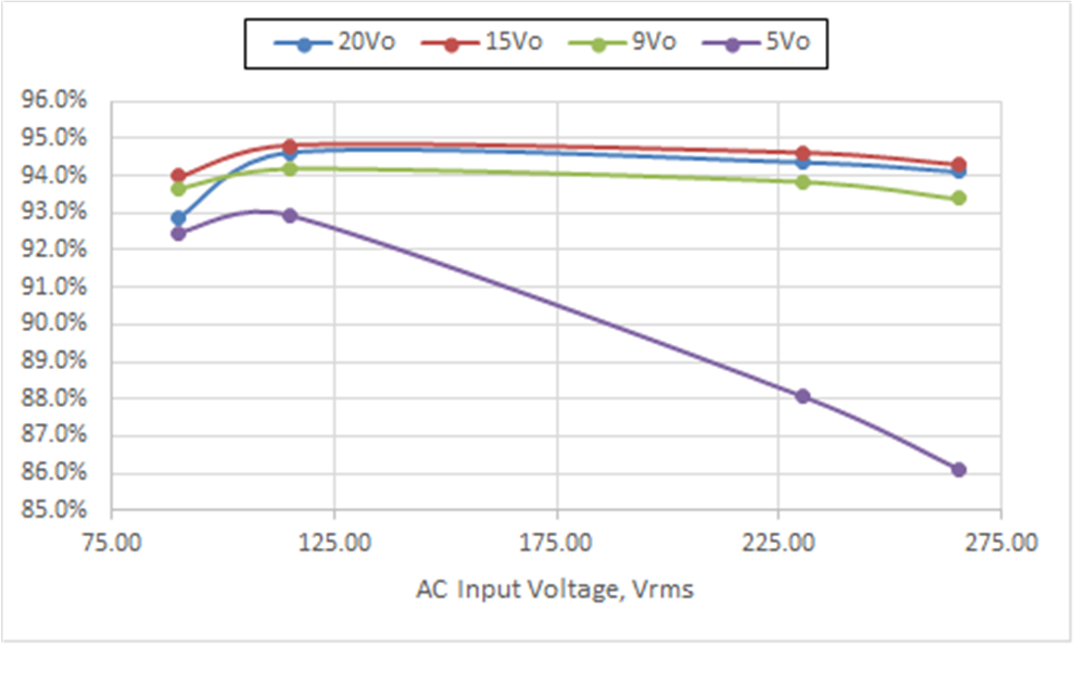 Figure 6-2 UCC28782EVM-030 Efficiency
Across Load
Figure 6-2 UCC28782EVM-030 Efficiency
Across LoadAs shown, the design exceeds CoC and DoE efficiency requirements. Additionally, the standby power consumption is kept at a minimum of 48 mW at 115-VAC input and 58 mW at 230-VAC input. This is achieved by the standby modes of operation of LMG2610 and UCC28782.
The thermals, captured at full load after 30 minutes, are shown in the following images.
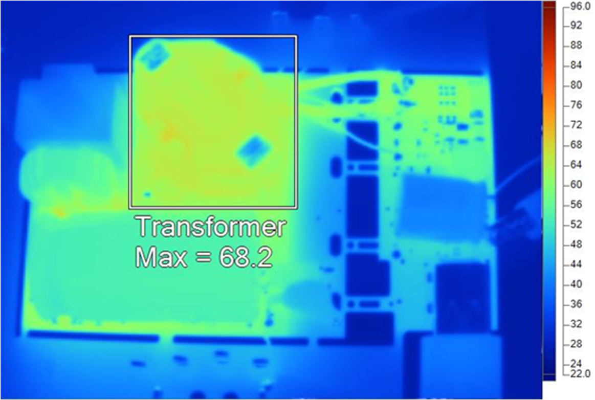 Figure 6-3 Vin = 115
Vac Top Side
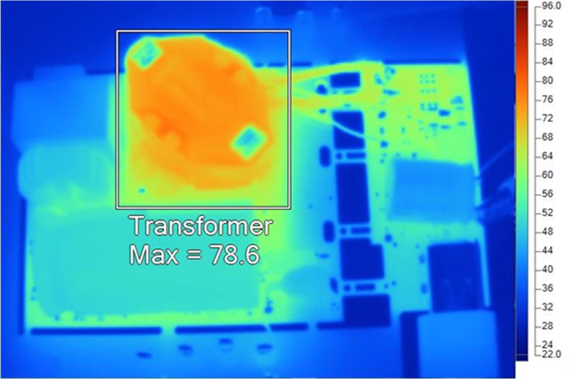 Figure 6-5 Vin = 230
Vac Top Side
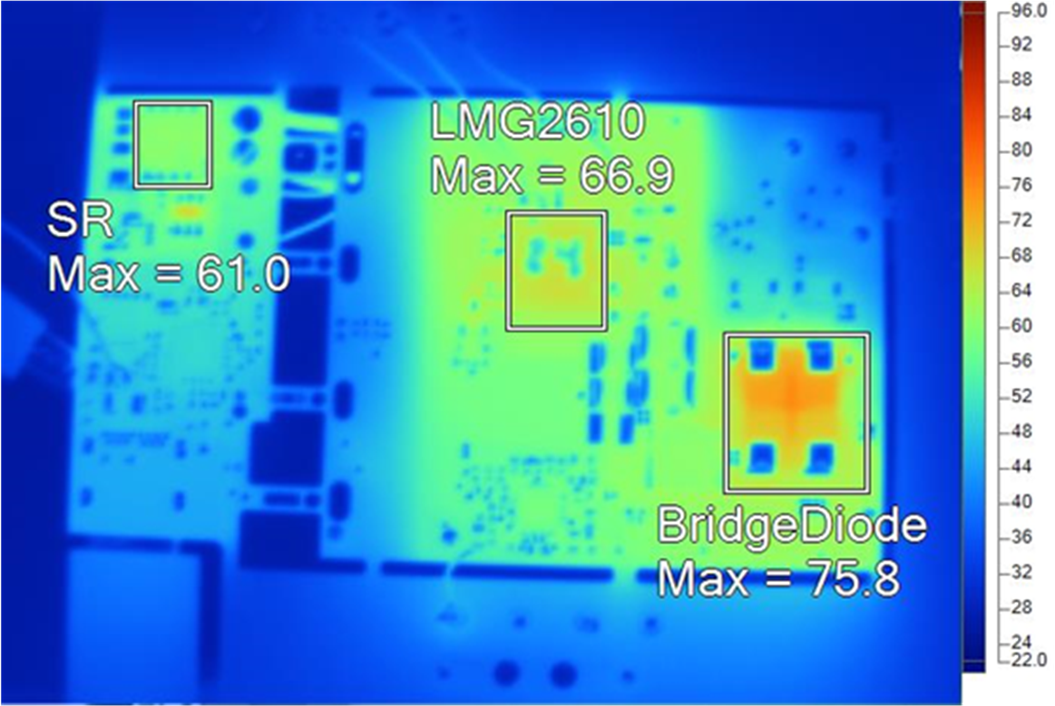 Figure 6-4 Vin = 115
VacBottom Side
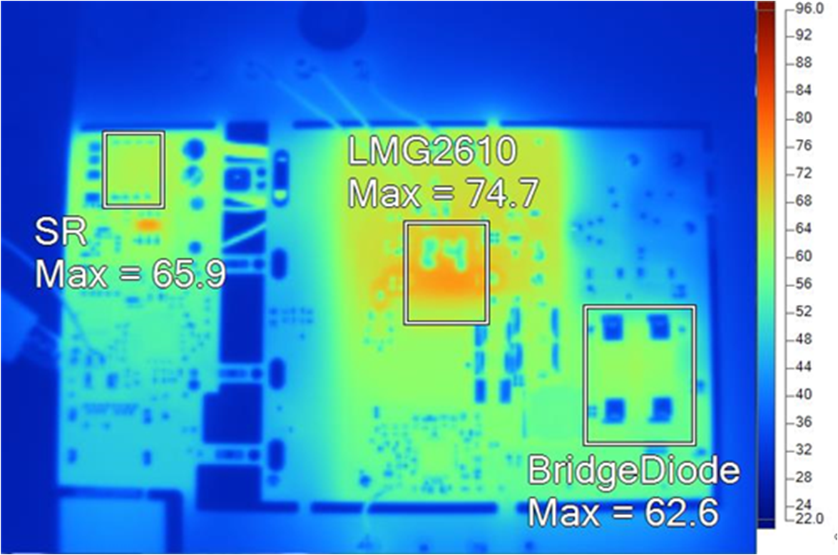 Figure 6-6 Vin = 230
Vac Bottom Side
Figure 6-6 Vin = 230
Vac Bottom SideTemperatures are managed all across the board to provide a thermally reliable operation. This is achieved through the previously discussed power-saving mechanisms such as ZVS, zero-clamp-loss, and current sense emulation.
In summary, this design achieves the small-form-factor goal by successfully managing thermals and switching at high frequency.