SLVAFI6 august 2023 TPS562242 , TPS563252 , TPS563257
2 An Overview of D-CAP3 Control Mode
D-CAP series control schemes are widely used in various electronic systems such as notebook, server, switches, Wifi-AP because of its fast transient performance, few external components for low cost and small design size.
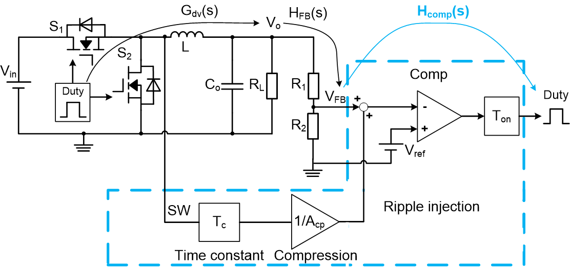
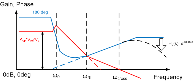
Diagram of buck converter with D-CAP2™ control scheme is shown as Figure 2-1. The bode plot of open loop transfer function for D-CAP2 converter is shown as Figure 5-6.
 Figure 2-1 Control Diagram of D-CAP2
Converter
 Figure 2-2 Bode Plot of D-CAP2 Converter
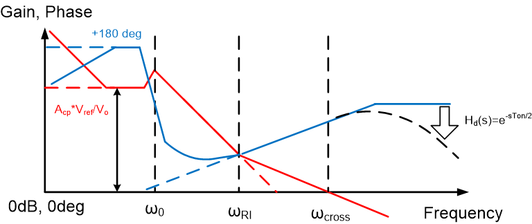
The D-CAP3 control mode is a variation of a constant-on-time control mode where the loop comparator monitors its inputs from the feedback voltage, reference voltage and emulated current ramp voltage to simulate ripple to generate on-pulses. To enhance DC accuracy of output voltage, D-CAP3 is proposed and widely used in TI’s current products. Compared with D-CAP2, the DC error correction performance is further improved in D-CAP3. By adding additional poles and zeros at low frequency range, the gain at low frequency range is increased to achieve better ability for DC error correction. But the characteristics of gain and phase at middle frequency and high frequency are almost same as D-CAP2 converter. The bode plot of open loop transfer function is shown as Figure 2-3. Stability Analysis and Design of D-CAP2 and D-CAP3 Converter – Part 1: How to Select Output Capacitor application note gives stability analysis and design of D-CAP2 and D-CAP3 converter.
 Figure 2-3 Bode Plot of D-CAP3 Converter