SLVAFT0 July 2024 DRV8706-Q1 , DRV8714-Q1 , DRV8718-Q1
2.1 Factors Affecting Bulk Capacitor Sizing
The amount of bulk capacitance needed depends on a variety of factors including:
- The highest current required by the motor system
- The power supply's type, capacitance, and ability to source current
- The amount of inductance between the power supply and motor system
- Method of operation, whether continuous or using pulse width modulation
- The acceptable supply voltage ripple
- Type of motor (brushed DC, brushless DC, stepper) and motor characteristics
- The motor startup and braking methods
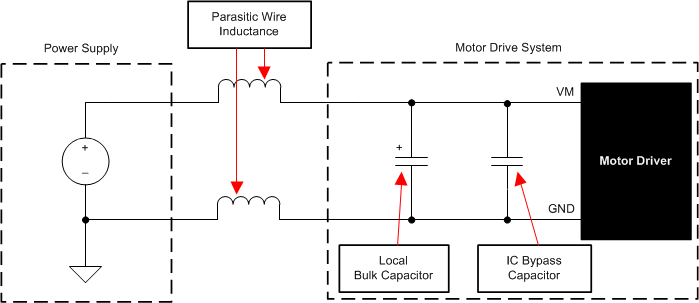
In a ideal DC motor system, there is no impedance between the motor drive circuit and the power source, which can be modeled as an ideal constant voltage source. In this ideal for case, there is not any variation in the motor supply voltage. However, in a real practical system, the inductance between the power supply and motor drive system limits the rate at which current from the power supply can change. There can also be filtering inductance on the driver board or in the power distribution network. This inductance between the power supply, often a 12V battery in automotive systems, and the motor drive voltage VM, is modeled as a lumped inductance on the positive and ground connections labeled Parasitic Wire Inductance shown in Figure 2-1.
If the local bulk capacitance is too small, the system responds to excessive current demands or dumps from the motor with a change in motor supply voltage. When adequate bulk capacitance is used, large variations in current can be quickly accommodated, and the motor supply voltage remains stable.
 Figure 2-1 Motor Drive Model From DRV8718-Q1 Data Sheet
The motor driver data sheet can provide a recommended minimum value, but system level testing is required to determine the appropriately sized bulk capacitor. Table 2-1 shows an example of the recommendations in a TI motor driver data sheet. Here both CPVDD1 and CPVDD2 are connected in parallel from the motor supply voltage (VM or PVDD) to Ground (GND).
| COMPONENT | PIN 1 | PIN 2 | RECOMMENDED |
|---|---|---|---|
| CPVDD1 | PVDD | GND | 0.1µF, low ESR ceramic capacitor, PVDD-rated. |
| CPVDD2 | PVDD | GND | Local bulk capacitance greater than or equal to 10µF, PVDD-rated. |
| CDVDD(1) | DVDD | GND | 1.0μF, 6.3V, low ESR ceramic capacitor |
| CAREF(1) | AREF(3) | GND | 0.1μF, 6.3-, low ESR ceramic capacitor |
| CVCP | VCP | PVDD | 1μF 16V, low ESR ceramic capacitor |
| CFLY1 | CP1H | CP1L | 0.1µF, PVDD-rated, low ESR ceramic capacitor |
| CFLY2 | CP2H | CP2L | 0.1µF, PVDD + 16V, low ESR ceramic capacitor |
| RnFLT | VCC(2) | nFLT | Pullup resistor, IOD ≤ 5mA |