SLVAFT0 July 2024 DRV8706-Q1 , DRV8714-Q1 , DRV8718-Q1
2.3 Estimating Motor Current Variation
During PWM operation, the motor current varies around an average value, with the current increasing during the on portion of the PWM period, and decreasing during the off portion. Modeling the motor winding as an inductance Lm in series with a resistance Rm, the increasing current is:
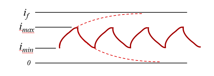
Where if is the final steady-state current at 100% duty cycle, typically PVDD/Rm and imin is the current at the beginning of the PWM on portion, and tau is the motor electrical time constant, Lm/Rm.
Similarly for the decreasing current:
Where imax is the current at the beginning of the PWM off portion.
The motor current variation in Equation 3 is the motor current variation over each PWM cycle. This is illustrated in Figure 2-3.
 Figure 2-3 Motor Current Variation During PWM Operation, Ideal Capacitors