SLVAFZ3 December   2024 DRV8161 , DRV8162 , DRV8350 , DRV8350F , DRV8353 , DRV8353F


  1.   1
  2.   Abstract
  3.   Trademarks
  4. 1Introduction
  5. 2System Power Requirements
  6. 3Motor Current and MOSFET Selection
    1. 3.1 How Does a BLDC Motor Driver System Work?
    2. 3.2 Motor Current and QG Value Relation
    3. 3.3 Role of a Motor Driver
    4. 3.4 Can my MOSFET be Driven or Commutated?
      1. 3.4.1 Example 1 – Medium Power (4.8kW – 48V × 100A)
      2. 3.4.2 Example 2 – High Power (19.2kW – 48V × 400A)
  7. 4Motor Driver Specifications to Consider
    1. 4.1 DRV8353 - Internally Generated Gate Drive Supply
    2. 4.2 DRV8161/DRV8162 – Externally Generated Gate Drive Supply
  8. 5Advantages of TI’s BLDC Drivers With Smart Gate Drive
  9. 6Maximum Source and Sink Current and QGD
  10. 7Older Designs
  11. 8Summary
  12. 9References

Motor Current and QG Value Relation

The current that can be delivered by the MOSFETs to the motor depends on the drain current (ID) rating of the MOSFET.

To turn on the N-type MOSFET one needs to apply a differential voltage across the gate and source of the FET to enhance the channel thereby creating a path for the current to flow from drain to the source. Figure 3-2 shows the schematic for an N-type MOSFET.
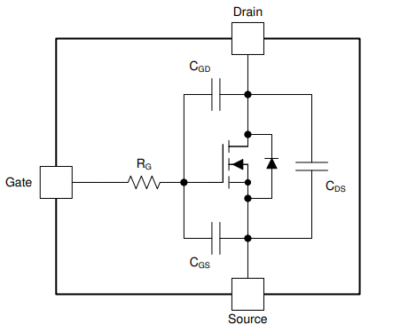
 MOSFET Circuit ModelFigure 3-2 MOSFET Circuit Model

To create this channel, the MOSFET's gate charge capacitance (Cg) needs to be charged up. Generally, the larger the current rating of the MOSFET, the larger the gate charge needed to turn on the MOSFET.