SLVUAK3C February 2016 – May 2021 TPS82130 , TPS82140 , TPS82150
4 Board Layout
This section provides the PWR720 EVM board layout and illustrations in Figure 4-1 through Figure 4-6. The Gerbers are available on the EVM product page: TPS82130EVM-720, TPS82140EVM-720, or TPS82150EVM-720. Rev B of the PCB just corrected typographical errors in the A version.
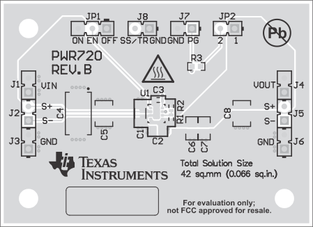 Figure 4-1 Top Assembly
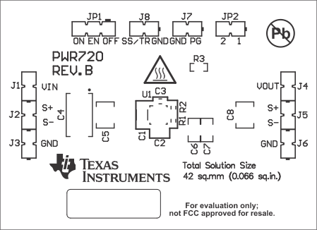 Figure 4-2 Top Overlay
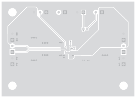 Figure 4-3 Top Layer
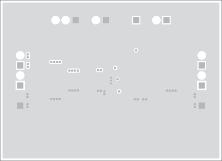 Figure 4-4 Internal Layer 1
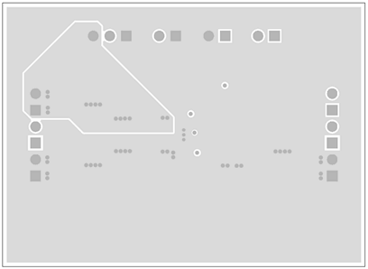 Figure 4-5 Internal Layer 2
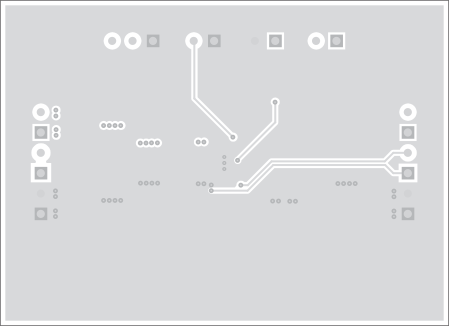 Figure 4-6 Bottom Layer