SLVUC37 March 2021 TPS25814
3.4 Switches: ADCIN1 and ADCIN2
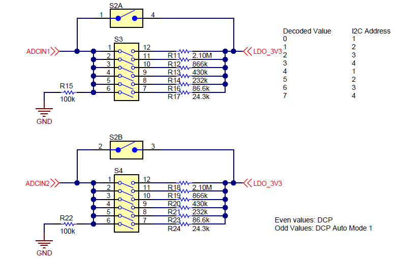
The TPS25814EVM has 3 switches (S2, S3, and S4) that can be used to configure the BusPowerZ setting of the device. As shown within the TPS25814 data sheet, there are eight different ADCINx decoded values ranging from 0 to 7. These three switches allow for control of these decoded values presented on both ADCIN1 and ADCIN2. Figure 3-4 shows these three switches.
 Figure 3-4 ADCINx Switches
Switches S2A and S3 are connected to ADCIN1, and switches S2B and S4 are connected to ADCIN2. When S2A or S2B are enabled, a decoded value of 7 will be presented on ADCIN1 and ADCIN2 respectively. For decoded value 0, disable all switches on S3 or S4, as well as S2. For a decoded value of 1 through 6, enable the wanted decoded value on switches S3 or S4. For example, for a decoded value of 3 for ADCIN1, enable position 3 on S3, having all other positions disabled on S3 as well as disabling S2A. For a decoded value of 7, enable S2A or S2B, with all all positions on S3 or S4 disabled. It is important to note that only one switch can be enabled at a time for normal operation.