SLVUCZ9 July 2024 DRV81004-Q1 , DRV81008-Q1 , DRV81620-Q1
2.2 Connector and Jumper Information
The DRV81xxx-Q1 family of devices is designed to drive low-side, and high-side loads. The following section explains how each EVM must be configured to drive the desired load.
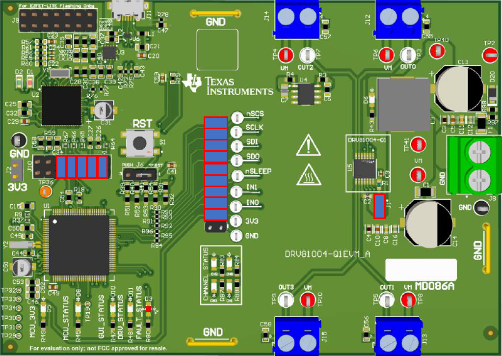 Figure 2-2 DRV81004-Q1 Jumper
Configuration
Figure 2-2 DRV81004-Q1 Jumper
ConfigurationJ1: Connects 3.3V to VDD.
The DRV81004-Q1 has four low-side switch outputs. Loads must be connected across blue output terminals OUT0-OUT3 accordingly.
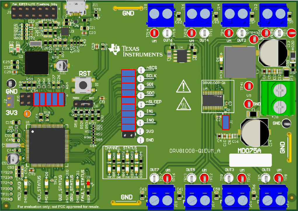 Figure 2-3 DRV81008-Q1 Jumper
Configuration
Figure 2-3 DRV81008-Q1 Jumper
ConfigurationThe DRV81008-Q1 has eight low-side switch outputs. Loads must be connected across blue output terminals OUT0-OUT7 accordingly.
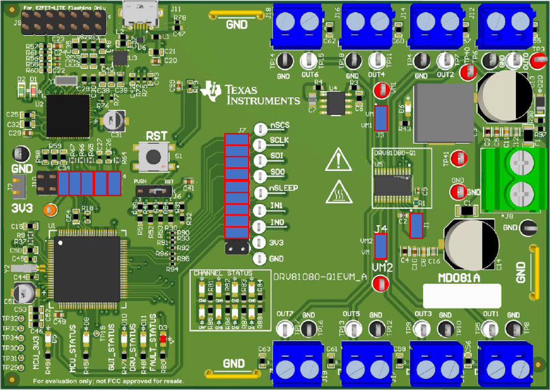 Figure 2-4 DRV81080-Q1 Jumper
Configuration
Figure 2-4 DRV81080-Q1 Jumper
ConfigurationThe DRV81080-Q1 has eight high-side switch outputs. Loads must be connected across blue output terminals OUT0-OUT7 accordingly.
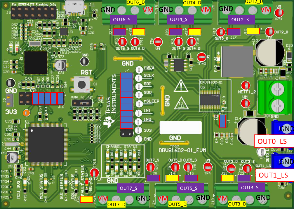 Figure 2-5 DRV81602-Q1 Jumper
Configuration
Figure 2-5 DRV81602-Q1 Jumper
ConfigurationThe DRV81602-Q1 has six configurable outputs that can be used as a high-side switch or a low-side switch. If an output is being used as a high-side switch then the yellow jumpers need to be populated and the load connected from OUTx_S to GND. If driving low-side loads, then the purple jumpers need to be populated and the corresponding load connected from OUTx_S to VM. If an output is being used as a low-side switch then the purple jumpers need to be populated and the load connected from OUTx_D to VM.
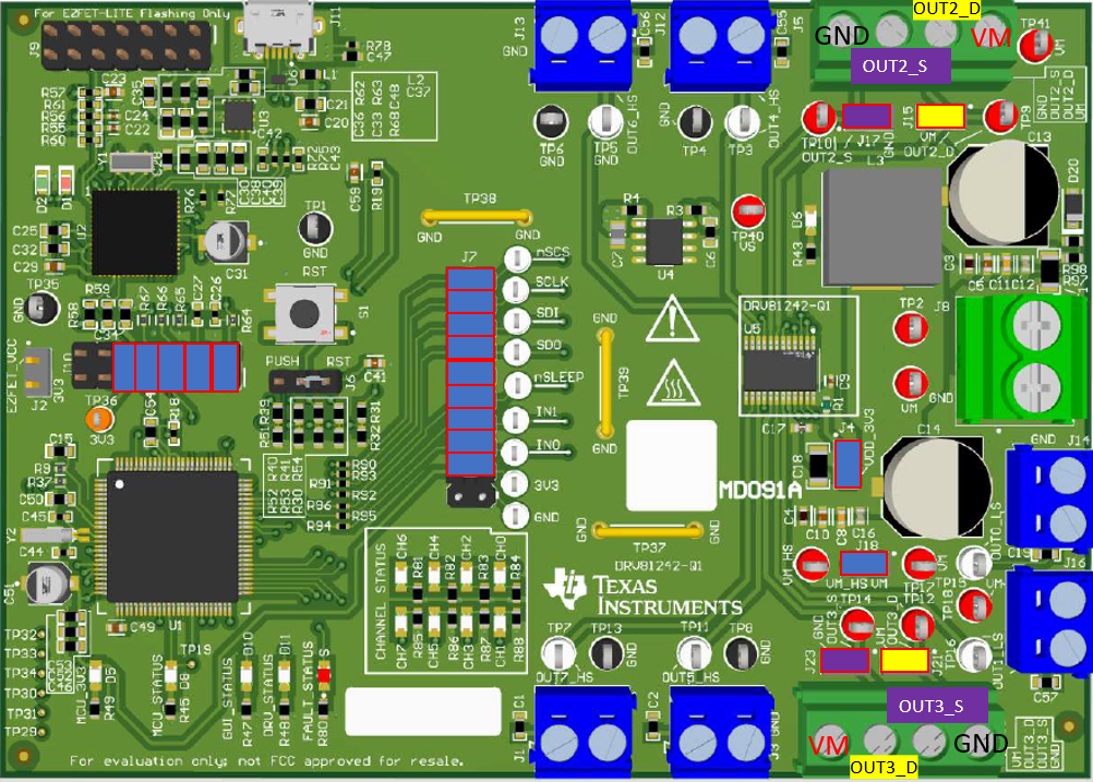 Figure 2-6 DRV81242-Q1 Jumper
Configuration
Figure 2-6 DRV81242-Q1 Jumper
ConfigurationThe DRV81242-Q1 has two configurable outputs that can be used as a high-side switch or a low-side switch. If an output is being used as a high-side switch then the yellow jumpers need to be populated and the load connected from OUTx_S to GND. If driving low-side loads the purple jumpers need to be populated and the corresponding load connected from OUTx_S to VM. If an output is being used as a low-side switch then the purple jumpers need to be populated and the load connected from OUTx_D to VM.
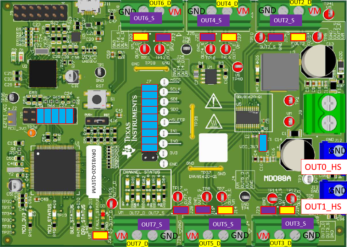 Figure 2-7 DRV81620-Q1 Jumper
Configuration
Figure 2-7 DRV81620-Q1 Jumper
ConfigurationThe DRV81620-Q1 has six configurable outputs that can be used as a high-side switch or a low-side switch. If an output is being used as a high-side switch then the yellow jumpers need to be populated and the load connected from OUTx_S to GND. If driving low-side loads the purple jumpers need to be populated and the corresponding load connected from OUTx_S to VM. If an output is being used as a low-side switch then the purple jumpers need to be populated and the load connected from OUTx_D to VM.
All EVMs require a VDD power supply for digital logic. Some of the configurable and high-side switch drivers require a jumper placement for additional power supply. See the table below for a description the device and jumper requirements.
| Device | Jumpers | Description |
|---|---|---|
| DRV81004 | J1 | Connects 3.3V to VDD |
| DRV81008 | J1 | Connects 3.3V to VDD |
| DRV81080 | J1 | Connects 3.3V to VDD |
| J3 | Connects VM to VM1 | |
| J4 | Connects VM to VM2 | |
| DRV81602 | J1 | Connects 3.3V to VDD |
| DRV81242 | J1 | Connects 3.3V to VDD |
| J18 | Connects VM to VM_HS | |
| DRV81620 | J1 | Connects 3.3V to VDD |