SLVUCZ9 July   2024 DRV81004-Q1 , DRV81008-Q1 , DRV81620-Q1


  1.   1
  2.   Description
  3.   Get Started
  4.   Features
  5.   Applications
  6.   6
  7. 1Evaluation Module Overview
    1. 1.1 Introduction
    2. 1.2 Kit Contents
    3. 1.3 Specification
    4. 1.4 Device Information
  8. 2Hardware
    1. 2.1 Header Information
    2. 2.2 Connector and Jumper Information
    3. 2.3 Hardware Setup
  9. 3Software
    1. 3.1 Software Setup
    2. 3.2 Web GUI Access or Local GUI Installation
    3. 3.3 Connecting EVM to GUI
    4. 3.4 GUI Overview
      1. 3.4.1 Low-Side Drivers: DRV81004-Q1 and DRV81008-Q1
      2. 3.4.2 High-Side Driver: DRV81080-Q1
      3. 3.4.3 Configurable HS/LS: DRV81602-Q1, DRV81242-Q1, and DRV81620-Q1
  10. 4Hardware Design Files
    1. 4.1 Schematics
    2. 4.2 PCB Layouts
    3. 4.3 Bill of Materials (BOM)
  11. 5Additional Information
    1. 5.1 Known Hardware or Software Issues
    2. 5.2 Trademarks

Header Information

This section describes the headers and test points for each variant of the DRV81xxx-Q1 family of devices.
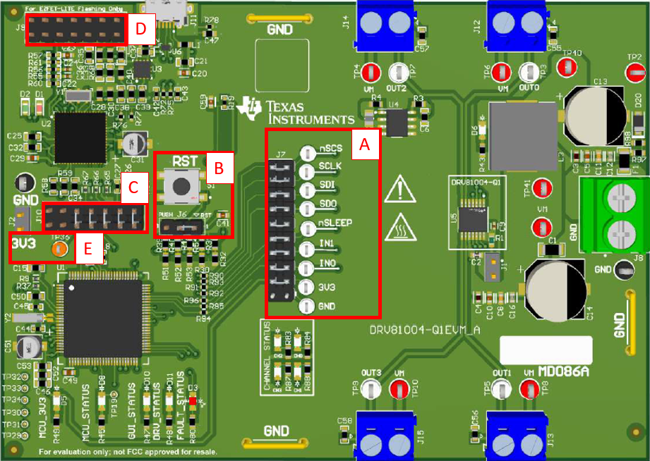
DRV81008-Q1EVM, DRV81602-Q1EVM, DRV81242-Q1EVM,  DRV81004-Q1EVM Headers and
                    Test Point Information Figure 2-1 DRV81004-Q1EVM Headers and Test Point Information
Component Label Description

A

Main signal header:

  • nSCS: Serial chip select.
  • SCLK: Serial clock input.
  • SDI: Serial data in.
  • SDO: Serial data out.
  • nSLEEP: Sleep mode input.
  • IN1: Control input IN1.
  • IN0: Control input IN0.
  • 3V3: 3.3V from LDO.
  • GND: GND test point.

B

Reset/PUSH button can have two functions based on the location of the SHUNT in J6 (below RST button):

  • RST (SHUNT in position 1): pressing the button resets the MCU.
  • PUSH (SHUNT in position 3): pressing the button does a suser defined action. Currently not implemented in firmware.

C

JTAG connector between MSP430F5338 and MSP430F5528.

D

Connector for programming MSP430F5528 used in the eZ-FET lite debugger circuit. Only used one time by PCB manufacturer to programmed eZ-FET lite debugger MCU.

E

3V3 LDO connector.
Note: All of the DRV81xxx-Q1EVMs have the same layout structure for A, B, C, D, and E as seen above.