SLYU064A June 2023 – December 2023 TMAG3001 , TMAG5170 , TMAG5170-Q1 , TMAG5170D-Q1 , TMAG5173-Q1 , TMAG5253 , TMAG5273
2.3 Design Calculations
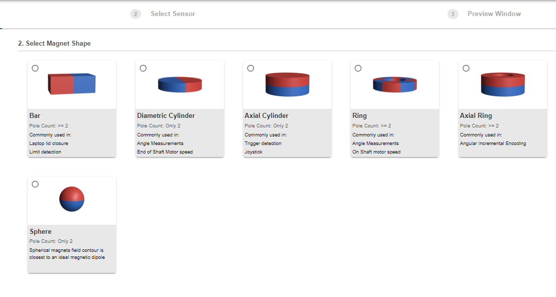
Having established general expectations of what output is needed for the design, the iterative process of finding the exact placement regions can now be executed. TI offers a Magnetic Sense Simulator to facilitate this process. This tool has a main menu, where the user can specify the type of magnet movement. The user selection then takes them to a sub-menu with entries to specify magnet placement, sensor placement, range of motion, and device of interest. Figure 2-9 shows the top menu and the Rotation movement sub-menu.
 Figure 2-9 Tool Menus
 Figure 2-10 Tool Menus
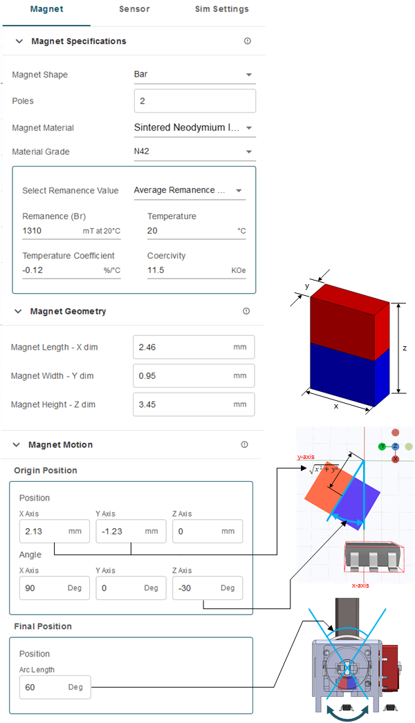
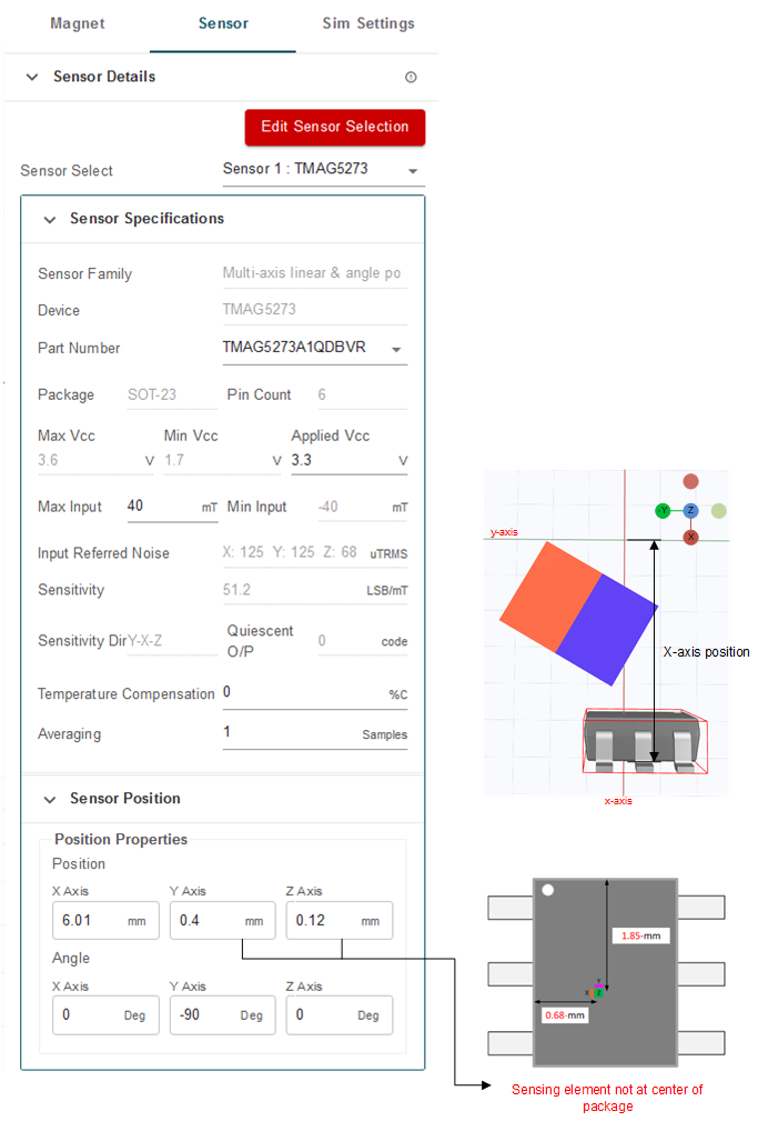
For the two-sensor thumbstick, the inputs required for the desired behavior are shown in Figure 2-11.
 Figure 2-11 2
Magnet and Sensor Thumbstick Input
 Figure 2-12 2 Magnet and Sensor Thumbstick
Input
 Figure 2-13 Tool Output for 2 Sensor Thumbstick Input