SNLA435A September 2023 – January 2024 DS320PR1601 , DS320PR410 , DS320PR810
3.5 CTLE Sweep Result
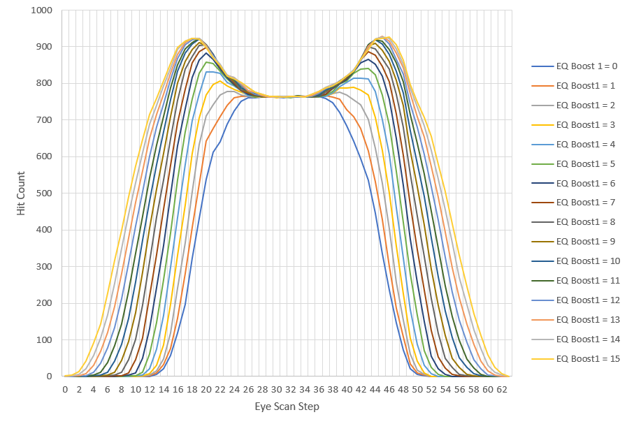
In real-world PCIe channel mediums, varying insertion loss must be compensated for. To compensate for varying pre-channel (before the redriver) insertion loss, a higher EQ boost must be applied by the redriver to compensate for added insertion loss. A visualization of some of the redriver’s EQ boost settings, specifically EQ Boost 1, using the Eye Scan feature and a plot is shown in Figure 3-6.
 Figure 3-6 Eye Scan Results of Varying EQ
Boost 1 Settings
Figure 3-6 Eye Scan Results of Varying EQ
Boost 1 SettingsAs EQ Boost 1 is increased, the shape of the Eye Scan plot changes in multiple ways. In Figure 3-6, we can observe that at a low EQ Boost 1 value (example, EQ Boost 1 = 0), the hit count flat region of the Eye Scan plot is relatively small and not accompanied by hit count peaks. However, as EQ Boost 1 increases, the Eye Scan plot begins to show two distinct hit count peaks with a distinct flat region between. The region between these hit count peaks is indicative of some vertical eye opening. While choosing the best EQ Boost settings can be challenging, in many applications the best EQ Boost settings show slight under-equalization at the redriver's transmitter. That is, when the hit count peaks are less defined, but above the minimum peak, a well-performing range of EQ Boost settings is selected.