SNLA435A September 2023 – January 2024 DS320PR1601 , DS320PR410 , DS320PR810
3.3 Programming Steps for Manual Eye Scan Capture
To programmatically capture the Eye Scan of varying equalization settings of the PCIe redriver, the following measures must be taken to verify that the capture is valid.
- Verify that the PCIe redriver is operating in either SMBus (I2C) Primary or Secondary Mode before powering on the device (MODE pin L1 or L2).
- Connect an I2C controller to the SDA/SCL pins of the PCIe redriver capable of meeting the redriver’s SMBus/I2C timing requirements (found in each device specific data sheet).
After powering on the PCIe redriver, the following steps can be taken to complete an Eye Scan sweep on a single channel. Please refer to device specific programming guides avaialble on ti.com for further device programming information.
- Verify that the redriver’s channel equalization settings (CTLE, Flat Gain)
are configured as desired using direct SMBus/I2C programming or
using the Texas Instruments SigCon Architect GUI, available on ti.com.
- If modifying PCIe redriver settings after PCIe link-up has begun or completed, make sure to perform a PCIe warm reset (exercising PERST#) or a PCIe link retrain to verify that the PCIe link has properly re-trained with the re-programmed redriver equalization settings.
- Verify that the PCIe link with the redriver has entered an active link-up
state (L0) at the desired data rate.
- An active-traffic PCIe link maintains that a valid Eye Scan is captured.
- Verify that the proper redriver channel to perform the Eye Scan capture on is selected.
- Set the desired DAC granularity on the redriver channel to sweep the desired voltage range.
- Begin sweeping the redriver channel’s DAC level, dividing each captured hit
count 32 to normalize for insignificant variations hit count values.
- Make sure to capture each DAC level’s hit count value captured by the redriver before changing the DAC level to gather valid hit count datapoints.
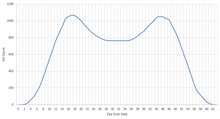
To visualize the captured Eye Scan for the redriver channel, plot each of the 64 DAC hit count values vs. DAC voltage level (or DAC step). This plot is a 90° counter-clockwise rotation of the vertical eye captured at the redriver’s transmitter. An example Eye Scan capture plot can be seen in Figure 3-4, where one EQ boost setting is selected for an Eye Scan capture, then each hit count data point is plotted.

Figure 3-4 Example Eye Scan Hit Count vs. DAC Step
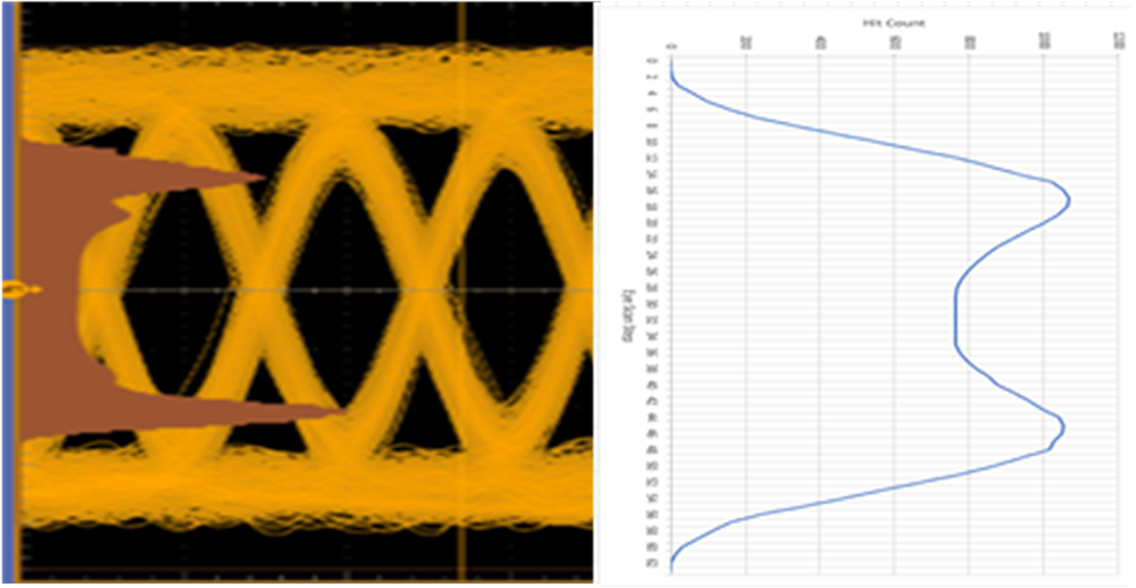
In Figure 3-4, a flat region is observed between the peaks of the hit count plot. This region represents an open portion of the vertical eye observed at the redriver’s transmitter. This can be correlated with an oscilloscope’s eye diagram capture of the same waveform directly after the redriver using the histogram feature of the oscilloscope to plot hits counted at each point along the vertical axis, shown in Figure 3-5. This comparison shows the strong correlation between the oscilloscope’s capture and Eye Scan’s capture of the vertical eye at the redriver transmitter. Please note that the oscilloscope histogram is not to scale.

Figure 3-5 Histogram Plot of Captured Eye After Redriver vs. Eye Scan Capture Plot