SNLU224D September 2017 – February 2023 DS90UB953-Q1 , DS90UB953A-Q1
- Trademarks
- 1Introduction
- 2Quick Start Guide
-
3Troubleshooting
- 3.1 Default Addresses
- 3.2 USB2ANY
- 3.3 ALP Software Setup
- 3.4
Troubleshooting ALP Software
- 3.4.1 ALP Loads the Incorrect Profile
- 3.4.2 ALP Does Not Detect the EVM
- 3.4.3 Error When Opening ALP: One Instance of this Application Can Be Active
- 3.4.4 Error Referring to USB2ANY Firmware Update
- 3.4.5 Identifying USB IDs and Corresponding Devices
- 3.4.6 Set up File for Loading Scripts and Create Buttons for Each Script
- 3.5 Additional Troubleshooting – Step-by-Step Guide
- 4Bill of Materials
- 5PCB Schematics
- 6Board Layout
- 7Related Documentation
- 8Revision History
3.5.2 EVM Equipment Setup
- Power ON the HP E3610A.
- Verify that CC SET is not on which is indicated by the illuminated light next to CV.
- Verify that RANGE is in 2-A mode which is indicated by the depressed RANGE button
- Use the Voltage knob to adjust the voltage to 12 V.
- Power OFF the HP E3610A
- Connect the red and black banana to coax cable from the + and – output of the HP E3610A, respectively, to the coax jack, J24, on the DS90UB954EVM (or variant) labeled 12 V. Alternatively, use the red and black banana to grabber cables from the “+” and “-“ output of the supply to pin 1 and 2, respectively, of J20, on the DS90UB954EVM (or variant) labeled GND and VDD_EXT near the lower left side of the board.
- Connect the FPD Link III cable from CN1 on the DS90UB954EVM (or variant) to J11 on the DS90UB953EVM. Ensure there is a click when connecting the cable to the connectors.
- Connect the Mini USB to USB cable from J5 on the DS90UB954EVM (or variant) to the computer that will use Analog Launch Pad (ALP).
- Connect the Mini USB to USB cable from J9 on the DS90UB953EVM to the computer that will use Analog Launch Pad (ALP).
- On the DS90UB954EVM (or
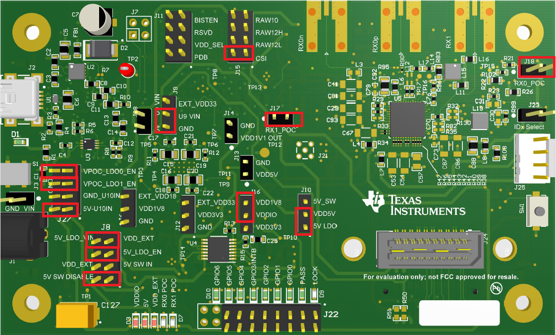
variant), ensure that all jumpers are correctly covering the headers highlighted
in #X9701.
 Figure 3-32 DS90UB954-Q1EVM (or variant) With Highlighted Jumpers
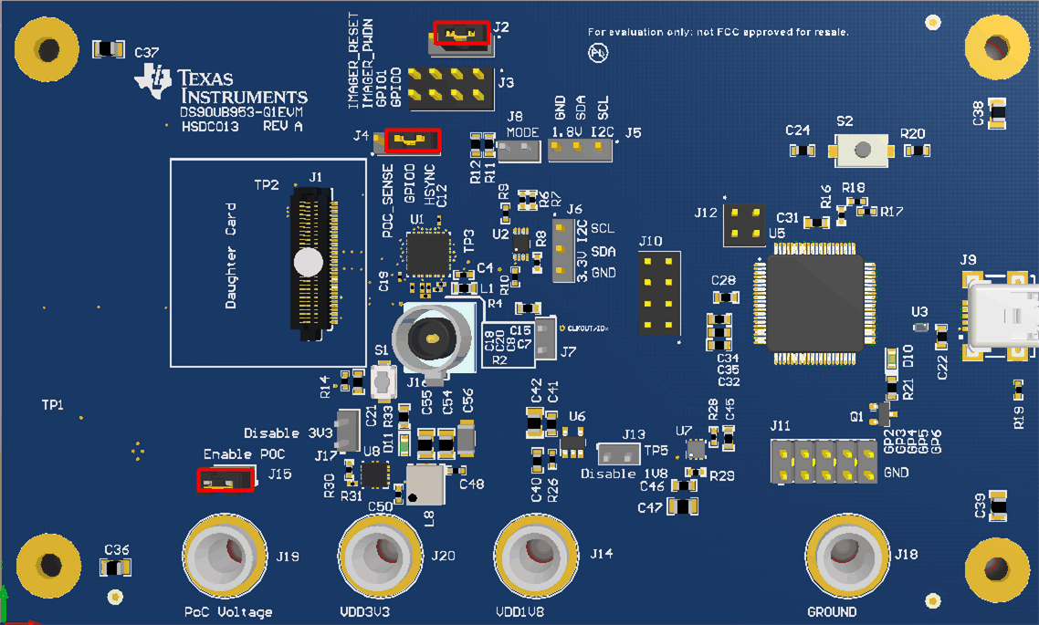
 - On the DS90UB953EVM,
ensure that jumpers are covering the headers as shown in #X6857.
 Figure 3-33 DS90UB95x-Q1EVM With Installed Jumpers
 - Power ON the HP E3610A.
- Verify that DS90UB953EVM is correctly powered by probing the banana jacks labeled PoC Voltage, VDD3V3, and VDD1V8 using a Digital Multi-meter (DMM). The voltages should approximately read ≥7 V, 3.3 V, and 1.8 V, respectively.
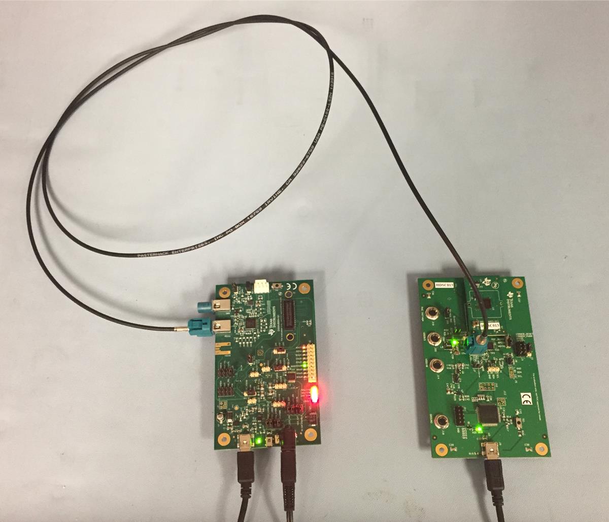
- The setup should now
look like what is shown in the #X1783.
 Figure 3-34 Test Setup
 - Ensure Analog Launch PAD (ALP) software is downloaded and installed correctly. One can download Analog Launch PAD from TI.com; note this requires a myTI Login. Steps for installation can be found in GUID-901EFD72-B326-4A4D-A71B-4E6EFE3504B9.html#GUID-901EFD72-B326-4A4D-A71B-4E6EFE3504B9
- Open the ALP software. If you receive an error
message about running the device in demonstration mode consult GUID-2D2110EC-A2F6-444D-82AE-C8DE8E2352A6.html#GUID-2D2110EC-A2F6-444D-82AE-C8DE8E2352A6. If you receive an error message about MainGUI.exe or having one instance of
the application open at once, consult GUID-3289CD3B-58C9-4A7D-996E-2714AE748E28.html#GUID-3289CD3B-58C9-4A7D-996E-2714AE748E28.
If you receive an error message about updating the USB2ANY firmware, consult GUID-6D62B0C4-7A98-4BF4-9C3F-09B7C1D8E4CE.html#GUID-6D62B0C4-7A98-4BF4-9C3F-09B7C1D8E4CE.
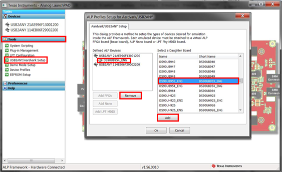
- Double click the Tools bar, then the
USB2ANY/Aardvark Setup, remove any devices that are not the 954 or 953 profiles
by selecting them and clicking remove. Note:
Be sure NOT to remove the USB ID or you will have to consult GUID-2D2110EC-A2F6-444D-82AE-C8DE8E2352A6.html#GUID-2D2110EC-A2F6-444D-82AE-C8DE8E2352A6.
Then select the appropriate device profile for the appropriate USB port using the scrolling menu on the right and clicking add as shown in #X1104.
 Figure 3-35 Setting up Device Profiles in ALP
 - If you are having trouble identifying which USB ID corresponds to a connected device, consult GUID-07AAB36E-F8DD-4B1E-B31A-5FF887F5F39C.html#GUID-07AAB36E-F8DD-4B1E-B31A-5FF887F5F39C.