SNOAAA5 April 2024 DRV8220 , FDC1004-Q1 , LDC3114-Q1 , TMAG5131-Q1 , TMAG5173-Q1 , TMAG6180-Q1
- 1
- Abstract
- Trademarks
- 1Introduction
- 2Automotive Door Handle Architectures
- 3Functional Demo Design
- 4Detailed Design Flow for Door Handle Functions
- 5Summary
- 6References
4.4.1 Inductive Push Buttons
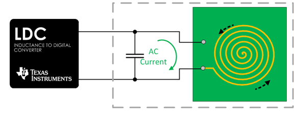
Inductive sensors operate on the principle of resonance between a variable inductor in the form of a sense coil, and a fixed, lumped-element (PCB) capacitor as illustrated in the following. The fixed capacitor and inductive coil form the external LC tank circuit required for LDC operation. The tank circuit resonates at a frequency dependent on the sense coil inductance and the fixed capacitance:
 Figure 4-23 Inductive Sensor Theory of
Operation
Figure 4-23 Inductive Sensor Theory of
OperationThe inductance of the sense coil varies in response to a nearby conductive object, which causes a shift in the LC tank resonant frequency, which the inductive sensing device (LDC) subsequently detects. For more information on inductive sensors, please see the Inductive Sensing Overview video, or the Common Inductive and Capacitive Sensing Applications, application note.
 Figure 4-24 Inductive Sensor Shift in
Resonant Frequency in Response to Target Movement
Figure 4-24 Inductive Sensor Shift in
Resonant Frequency in Response to Target MovementPush-button applications have long been implemented with mechanical switches that force electrical contacts together and (hopefully) make a low resistance connection. Even with their long history, mechanical switches can be prone to environmentally-induced failures, as well as wear-and-tear. Harsh environments can lead to intrusion and contamination (via dirt, oil, water, and so on) and can require special housings, gaskets, and other fittings to avoid premature failure. Robust, sealed mechanical switches that are resistant to contaminants are achievable, albeit at increased cost.
Push-button switches based on inductive sensing (LDCs) show very few of these shortcomings. The switches are robust and not subject to the inevitable failures associated with moving parts and worn contacts due to wear-and-tear from repetitive movement. The switches can be easily made immune to contaminants, and maintain reliability even in wet environments. The switches can accommodate spacious form-factors (to support users with gloves) or small form factors for limited space.
Some devices and designs can also support multilevel push buttons, and some have internal algorithms to manage multiple button-presses as well as mechanical distortions, freeing the microcontroller from managing those functions.
Inductive touch-buttons can be easily implemented with three main components: an inductive sensor, a target surface, and an inductance-to-digital converter (LDC). The sensor can frequently be implemented by a PCB-based or flex-circuit based coil. The target can be a flexible, conductive material, like thin metal with enough thickness to support skin-effect eddy currents.
A shown in Figure 4-25, a force applied on the target surface causes the material to deflect slightly, reducing the distance (DTARGET) between the inductive sensor and the target surface. The deflected conductor reduces the sensor inductance, which in turn causes the sensor resonant frequency to increase which is detected by the LDC. As a target deflection example, with an applied force of 1 Newton, a button with a 20-mm diameter can deflect about 0.1μm if the target material is 430 stainless, 1-mm thick. When the force is removed, the button surface returns to the original shape.
 Figure 4-25 Inductive Touch Button
Components