SNVU875A October 2023 – February 2024 TPS38700 , TPS389006
4 TPS389387EVM Evaluation Instructions
Equipment Needed
Hardware Equipment Needed for TPS389387EVM Evaluation:
- TPS389387EVM
MSP430 LaunchPad™, MSP-EXP430FR2355
- MSP430 connector/power cable (USB to micro-USB)
- Multi-channel oscilloscope to review evaluation waveforms
- Jumper cables for additional evaluation
Software Needed for TPS389387EVM Evaluation:
- A zip file contained editable code that controls the TPS389387EVM. This can be downloaded here.
- Code Composer Studio IDE (CCS), CCS v8.0 or higher. Code Composer Studio Desktop is a professional integrated development environment that supports TI's Microcontroller and Embedded Processors portfolio. Code Composer Studio is comprised of a suite of tools used to develop and debug embedded applications. Code Composer Studio includes an optimizing C/C++ compiler, source code editor, project build environment, debugger, profiler, and many other features. Learn more about CCS and download at Code Composer Studio.
Hardware Setup
Follow the steps below for the hardware setup:
- Attach the MSP430 to the pins at the bottom side of the TPS389387EVM. The orientation is detailed in TPS389387EVM Board Bottom with MSP430. Make sure that the GND pins match the corresponding board connector.
- Connect the power cable to the MSP430 and USB port of the computer.
- Make sure all jumpers are connected as per the guidelines in Table 3-2.
Software Setup
- Download Code Composer Studio IDE (CCS) to edit the code for this EVM.
- There is a cloud composer available, but this is not necessary.
- CCS can ask if additional components are needed. Please select the MSP430 option before proceeding to download.
- Download the code required to evaluate the EVM.
- Launch CCS and import the code into the workspace. Refer to the CCS Getting Started instructions on ti.com for additional help.
- When CCS has been launched, select a workspace directory. This defines the location of your project on your operating system.
- Use Project>Import Existing CCS Eclipse Project. Go to the desired demo project directory that contains main.c. This is illustrated in Figure 5-1.
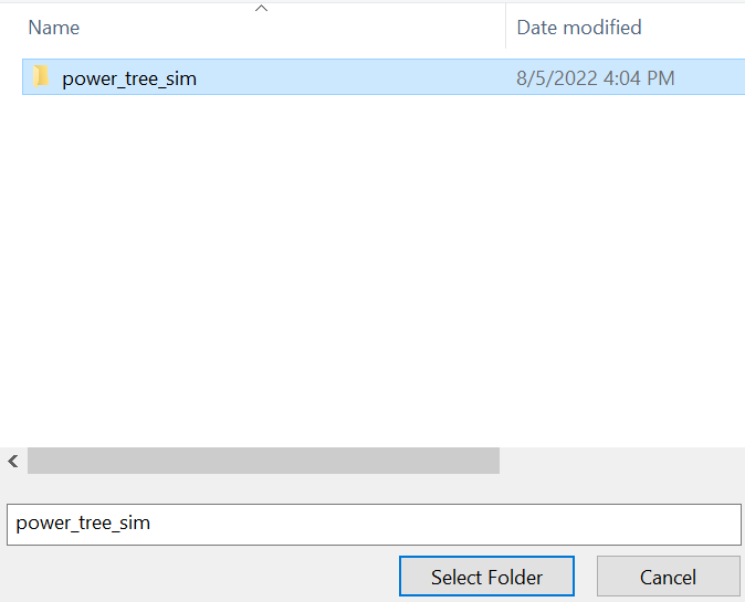 Figure 4-1 Selecting the Project Directory in CCS
 - Click OK.
- CCS recognizes the project and allows the user to import. Check to make sure the CCS has found the project, by looking for a checkmark to the left of the project name. This is shown in Figure 5-2.
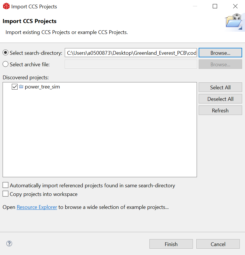 Figure 4-2 Recognizing the Project in CCS
 - If CCS does not show a checkmark, then this means that your workspace already has a project by that name. Resolve this by renaming or deleting that project.
- At this point, the code is fully uploaded to CCS. The workspace looks like Figure 5-1.
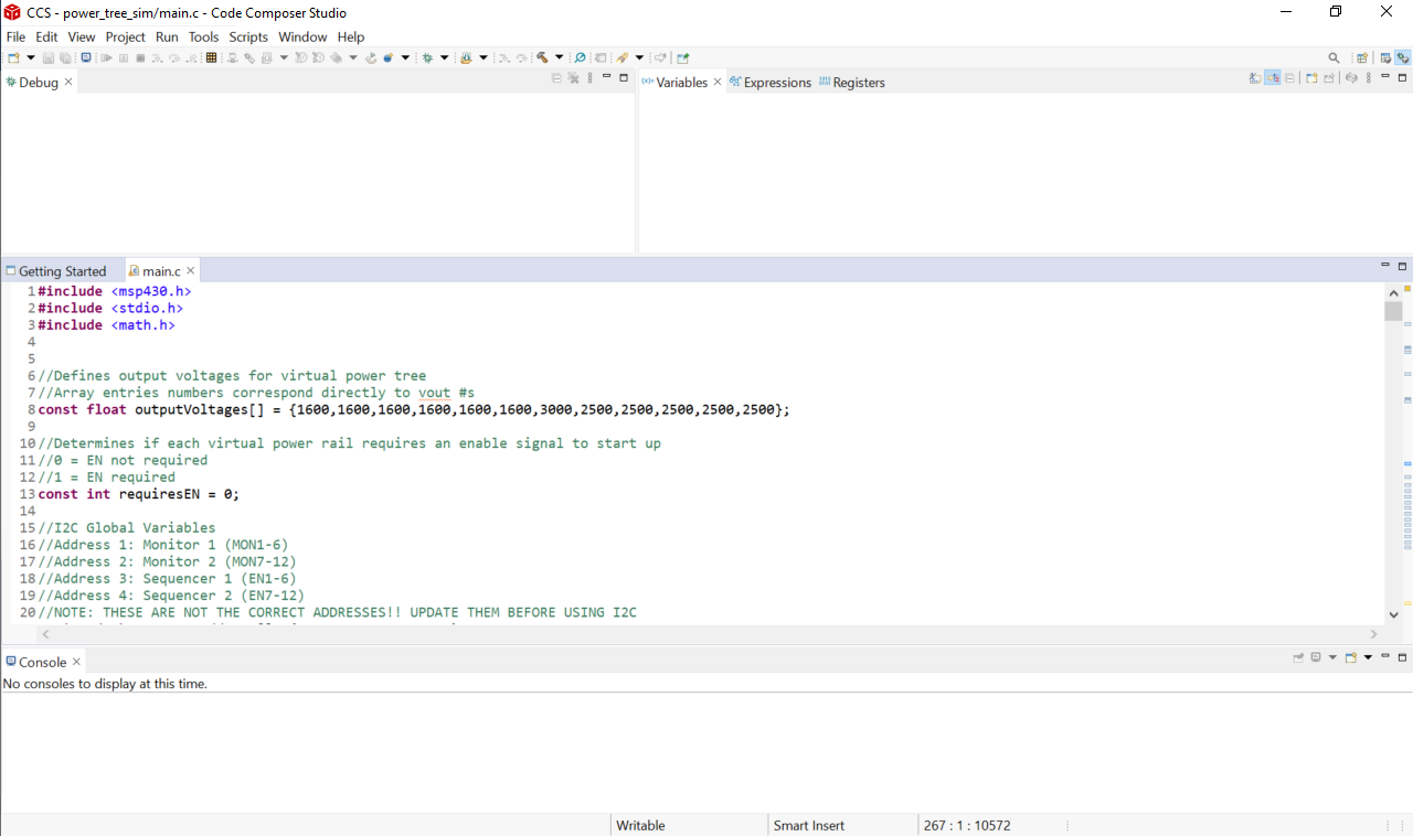 Figure 4-3 CCS Workspace with Code Uploaded
 - Edit the code to confirm correct operation.
- To change the output voltages for virtual power tree, edit line 8. This line reads as follows:
const float outputVoltages[] = {1600,1600,1600,1600,1600,1600,3000,2500,2500,2500,2500,2500};
Each of the values within the brackets correspond to the Vout for the TPS389006’s power monitor rails. These values are all in millivolts.
- To change whether each virtual power rail requires an enable signal from the sequencer to start up, edit line 13. This line reads as follows:
const int requiresEN = 0;
If the value after the "=" is a 0, then an enable signal from the sequencer is not required. If this value is set to 1, then an enable signal from the sequencer is required to start up.
- To change the output voltages for virtual power tree, edit line 8. This line reads as follows:
- Run the code by selecting Run> Start Debugging in the CCS workspace. See Figure 5-4 for more information.
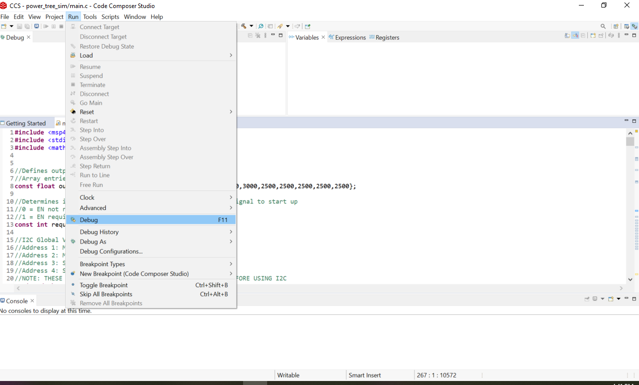 Figure 4-4 Run Code in CCS
 - Once the code is run, confirm correct operation.
- Check output voltages by measuring waveforms resultant from connections between pins in the header (J18) and oscilloscope. For more clarity on the pin locations, look at the schematic or Figure 3-1.
- Determine correct operation of Enables and Interrupts by examining the LEDs on the EVM. See LED functionality in Table 3-1.
- By pressing and holding button S1 on the MSP430 launchpad, the sequencer powers down the voltage rails in sequence. Releasing the button causes the power rails to power up in sequence. The power up and power down sequence can be checked by connecting an oscilloscope to the enable outputs of header J18.
- Figure 5-5 shows correct operation of the first three enable signals in the power up sequence and the corresponding sync pulses from the TPS389006.
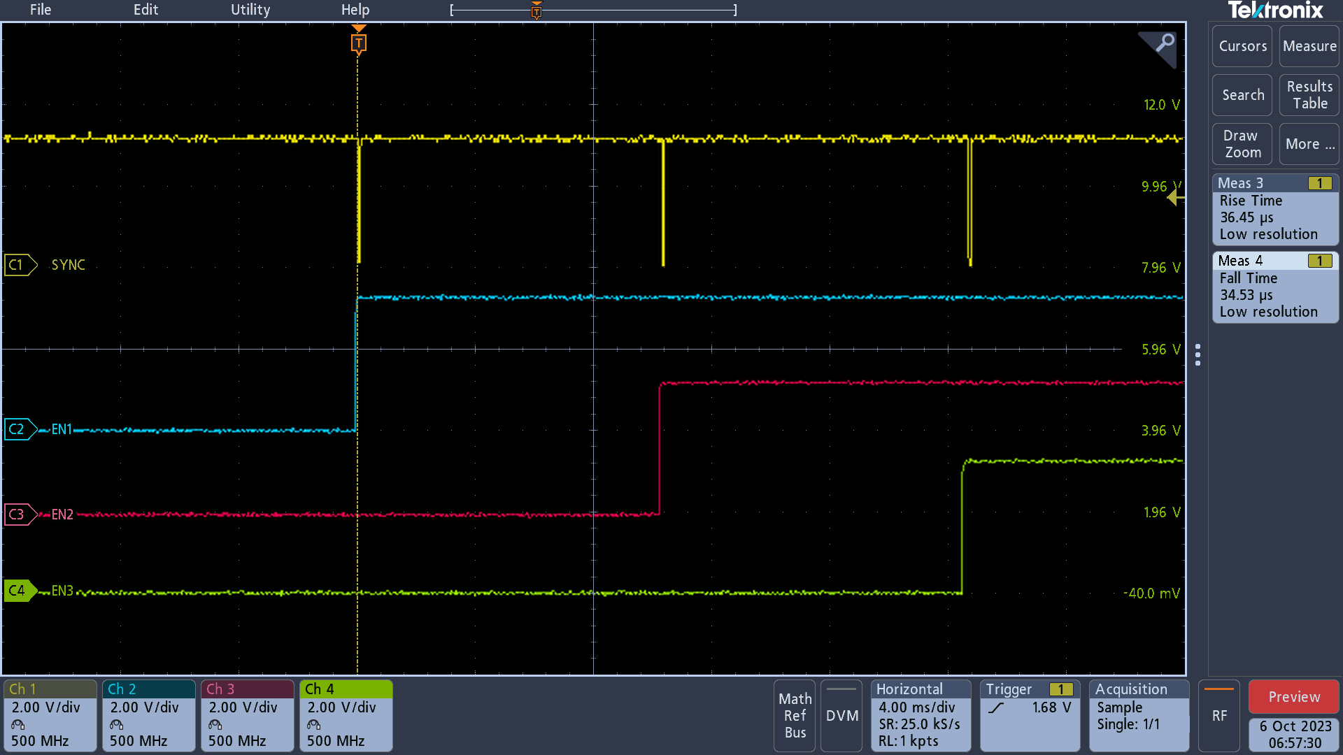 Figure 4-5 Power Sequence Up with Sync
 - Figure 5-6 shows correct operation of the first three enable signals in the power down sequence and the corresponding sync pulses from the TPS389006.
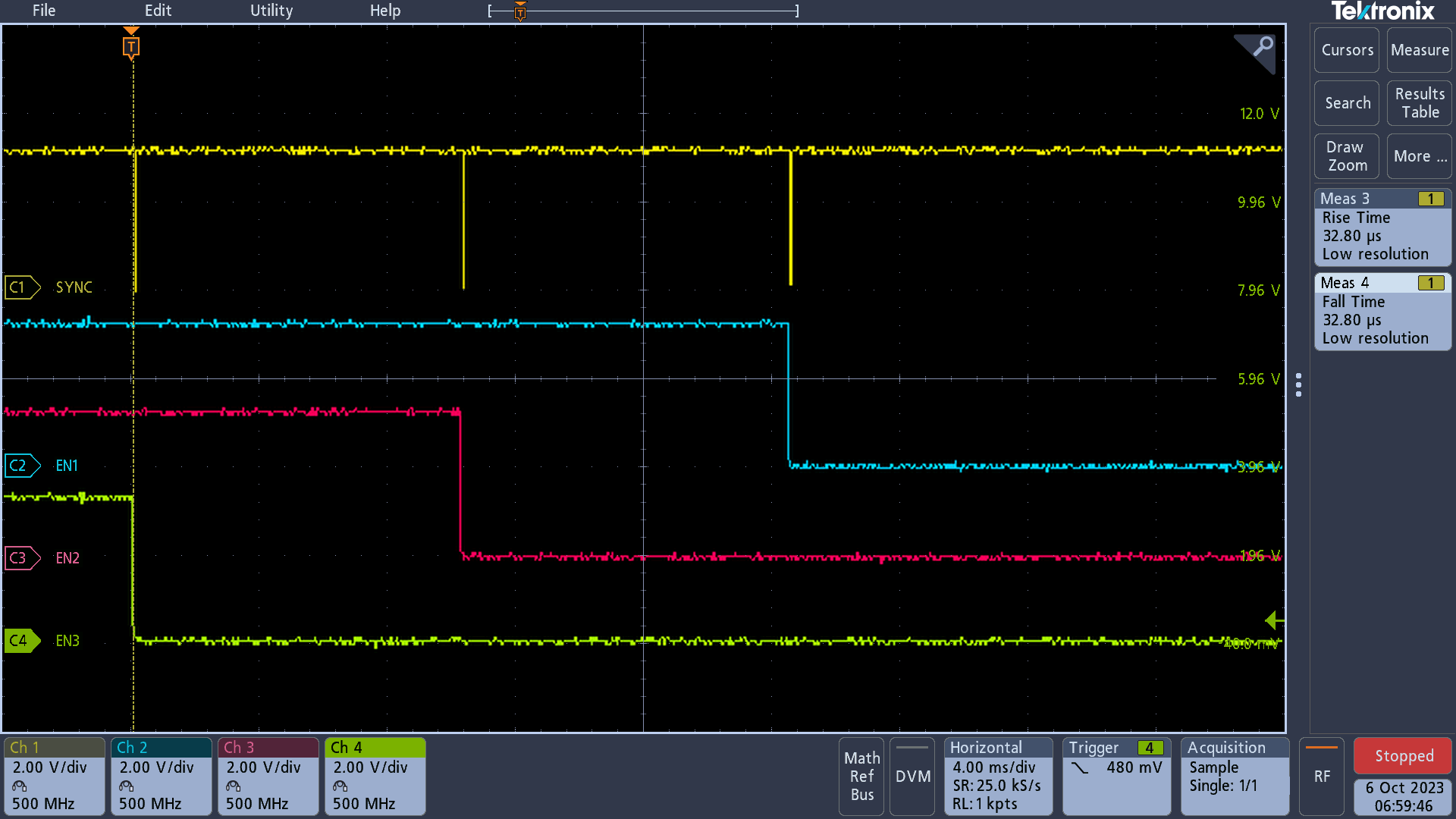 Figure 4-6 Power Sequence Down with Sync
 - Figure 5-7 shows where to place the oscilloscope probe on the EVM to view the sync signal. Place the probe on the terminal of R30 closest to device U2.
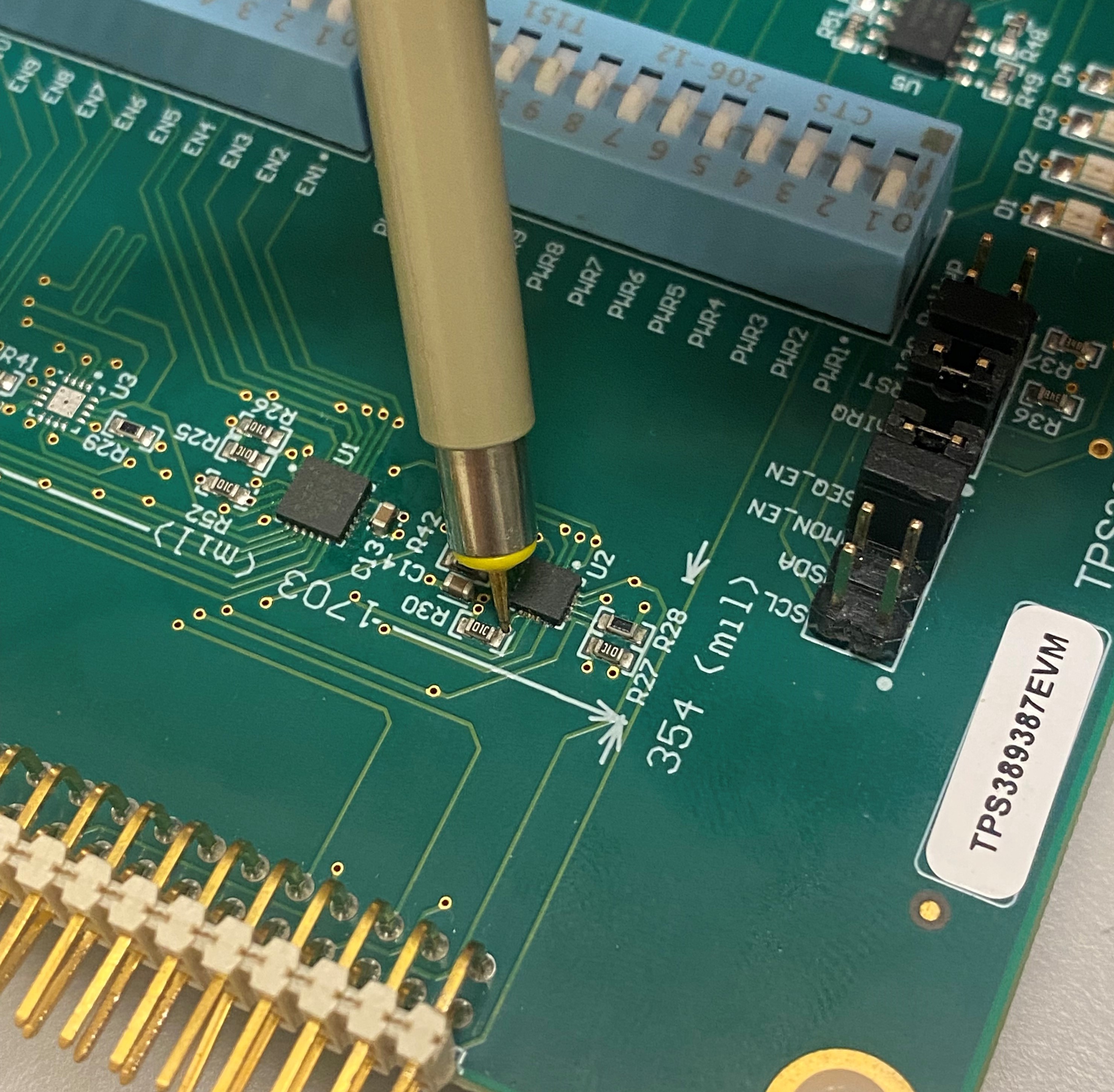 Figure 4-7 Sync Signal Probe
- The dipswitches can also be used to manually test the functionality of the device interrupts and enables.
- LED1 (D1) turns on in the case of an interrupt. This can be tested by using the dipswitches that control the TPS389006 power rail (SW1). When these dipswitches are flipped to the off position, the respective rail is manually turned off, resulting in an interrupt and turning on LED1.
- LED2 (D2) turns on when Enable 1 is activated. This can be tested using the dipswitches that control the TPS38700S-Q1 Enables (SW2). When these dipswitches are flipped to the off position, the respective EN is manually turned off, resulting in LED2 to turn off.
- LED3 (D3) and LED4 (D4) turn on when Enable 2 and Enable 3 are activated, respectively. This can be verified in the same way as LED2.