SSZT896 November 2017 LM25119 , LM5140-Q1
The increase in automotive infotainment performance and functionality demands a corresponding increase in processor power, precise voltage regulation, and accurate system protection and monitoring. TI offers many low-voltage power-management ICs (PMICs) for processor, double data rate (DDR) and auxiliary voltage-rail regulation. Low voltage in this case means that their input voltage is a low-input voltage like 3.3V or 5V.
So what powers these PMICs? One go-to solution is an Automotive Electronics Council (AEC)-Q100 automotive-qualified dual buck pulse-width modulation (PWM) controller.
The dual buck PWM channels can power both the PMIC (which in turn powers the processor and other lower-voltage rails) as well as another subsystem like the USB ports. Figure 1 shows a typical automotive dual buck controller application.
 Figure 1 Automotive-qualified Dual Buck
Controller Powering the Downstream PMIC and USB Type-C™
Figure 1 Automotive-qualified Dual Buck
Controller Powering the Downstream PMIC and USB Type-C™In Figure 1, the dual buck controller is the LM25119-Q1. This device can operate at a frequency between 50kHz and 750kHz, which enables you to select an operating frequency that avoids the AM band. The LM25119-Q1 offers a selection of 500kHz for this goal.
The LM25119-Q1 also interleaves the two buck channels, reducing the input current ripple and number of capacitors while reaping the associated power density and cost savings benefits. A lower root-mean-square (RMS) input current reduces the self-heating of the input capacitors and enables better thermal performance. It also lowers the amount of capacitance needed to keep the input voltage ripple within specifications.
Figure 2 shows the reduction in input current ripple.
 Figure 2 Input Current-ripple Reduction
via Phase Interleaving
Figure 2 Input Current-ripple Reduction
via Phase InterleavingYou can use the LM25119-Q1 RT pin (pin 13) to synchronize the internal oscillator to an external clock. This can be beneficial in terms of controlling and reducing the harmonics and beat frequencies, as more than one voltage regulator can operate at the same frequency provided by the external clock.
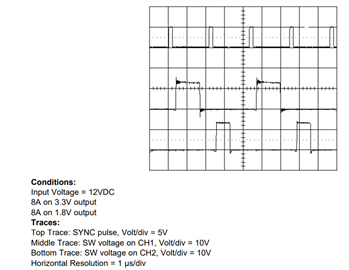
Figure 3 shows the external clock synchronization. Each channel is synchronized to the falling edge of the clock and both channels operate 180 degrees out-of-phase from each other, enabling the input current-ripple reduction benefits that I mentioned earlier.
 Figure 3 External Synchronization of
the LM25119-Q1 Channels
Figure 3 External Synchronization of
the LM25119-Q1 ChannelsYou can also use the LM25119-Q1 to power a PMIC, as well as a second rail like a USB Type-C port that requires 5V.
The TI USB Type-C Dock Reference Design is such a USB Type-C design. Note that the input voltage to the dual PWM buck controller is 20V, which is easily handled by the input voltage range with a maximum of 42V.
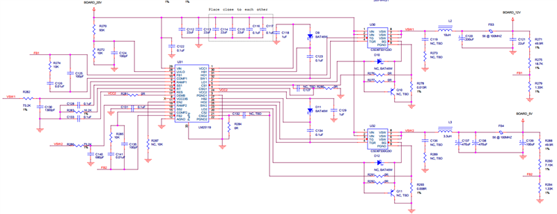
This specific design is nonautomotive, but it is possible to use the LM25119-Q1 in place of the LM25119 device, along with the appropriate selection of Q100 metal-oxide semiconductor field-effect transistors (MOSFETs) and other components. In this particular design, the LM25119 powers a 12V rail as well as a USB Type-C port at 5V, as shown in Figure 4.
 Figure 4 LM25119 Dual Buck Design for
12V and USB Type-C Port (5V)
Figure 4 LM25119 Dual Buck Design for
12V and USB Type-C Port (5V)The LM25119-Q1 also comes with WEBENCH® design support, and you can use the LM25119 evaluation board to evaluate the LM25119-Q1 controller.
In addition to the LM25119-Q1, the newly released LM5140-Q1 is another controller with WEBENCH design support that features ultra-low Iq and 2.1 MHz switching frequency, which is popular in automotive applications. You can use the LM5140 evaluation board to evaluate the LM5140-Q1 controller.
So if you are designing an automotive power system and have the need to power lower-voltage rails like 3.3V and 5V from a 12V input source – or have a 20V input source and need to also generate the 12V rail – the LM25119-Q1 and LM5140-Q1 dual PWM buck controllers with phase interleaving and frequency synchronization should be the go-to buck controllers in your design tool kit.