-
PFC Controller Step-by-Step Selection Guide
PFC Controller Step-by-Step Selection Guide
From consumer electronics gadgets like laptop to industrial equipment like robotics, anything powered from the AC grid represents a complex load condition and can behave more than just a pure resistor. If the load impedance includes an inductive or capacitive part, the input current is no longer in phase with the instantaneous line voltage, as shown in #FIG_UHX_VTJ_FWB. If the load only takes DC input and diode bridge + input cap is used to provide the DC input, the current will only be conducting when the AC voltage exceeds the DC voltage on the capacitor and the waveform is shown in #FIG_CJR_WTJ_FWB. Both cases incur apparent power transferred between the load and the supply, which demands higher peak power from the grid and wastes energy through the transmission line.
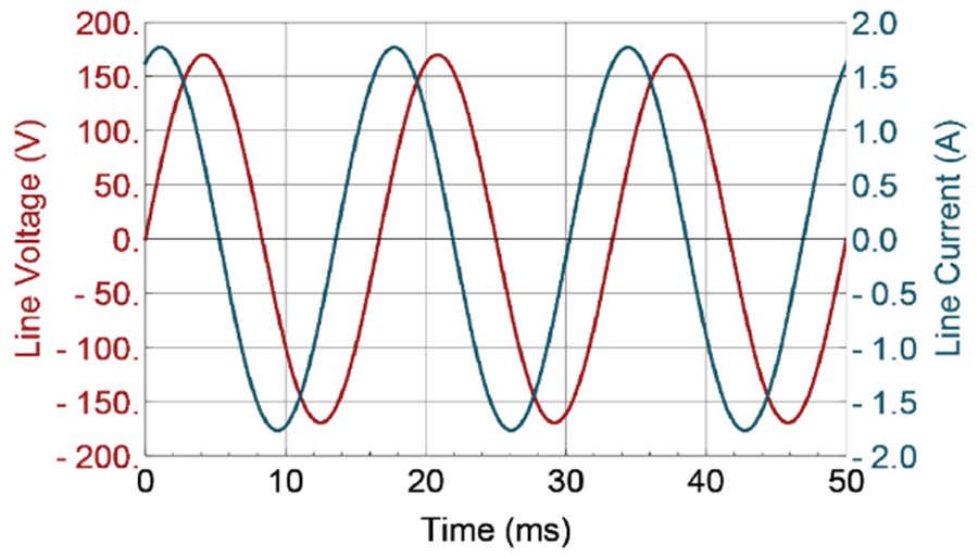 Figure 1-1 Input Voltage and Current Waveform for an Inductive Load
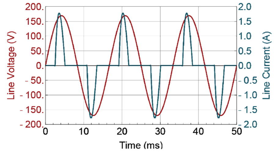 Figure 1-2 Input Voltage and Current Waveform For Diode Bridge Rectification
Therefore, a power factor correction (PFC) circuit between the load and the grid is needed to shapes the input current to be in phase with the instantaneous AC line voltage to minimizes the energy loss. The PFC function can be achieved through either passive or active means. A passive PFC circuit is comprised with only capacitors and inductors, which can be affordable and simple for certain scenarios, but it is challenging to achieve greater than 0.9 PF value across wide operating conditions. In contrast, a modern active PFC circuit can easily achieve PF value > 0.99 with efficiency greater than 97%.
TI offers variety of PFC solutions and the most common topology is the boost, as shown in #FIG_WGD_XTJ_FWB. The PFC stage resides between the DC/DC and rectified AC line. Because the boost inductor inherently limits the dI/dt of the input current, it makes the topology better equipped to achieve low input current distortion.
The boost PFC has three operation modes based on the inductor current waveform shape: Discontinuous Conduction Mode (DCM), Critical Conduction Mode (CrCM) and Continuous Conduction Mode (CCM). The CrCM is also referred as Transition Mode (TM) in some literature. The inductor current waveform is show in #FIG_XP1_55J_FWB for each mode. One key distinction of DCM and CrCM is that the current always reaches to zero in each switching cycle, where it doesn’t in CCM.
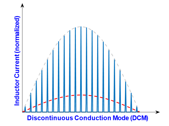 Figure 1-4 Inductor Current Waveform
for DCM Operation
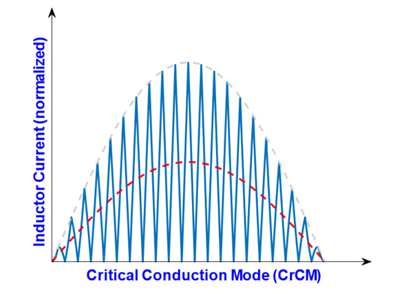 Figure 1-5 Inductor Current Waveform
for CrCM Operation
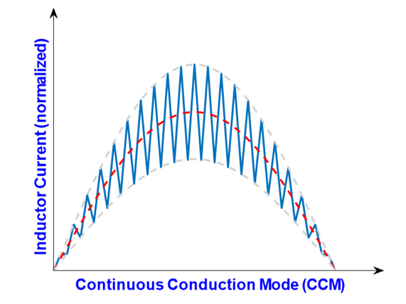 Figure 1-6 Inductor Current Waveform for CCM Operation
Table 1-1 highlights the pro and con of each operation mode. In short, DCM/CrCM is more suitable for low power applications and CCM is more suitable for high power applications. Nowadays, CrCM is more popular than just DCM controller because CrCM can deliver more power and the design complexity can be easily addressed by sophisticated IPs with little cost adder. Therefore, this guidebook will focus on CrCM and CCM controllers.
| Mode | Key Distinctions | Pro | Con |
|---|---|---|---|
| DCM |
|
|
|
| CrCM |
|
|
|
| CCM |
|
|
|
If more power is needed, a practical approach is to interleave two boost power stages that are operated 180° out of phase from each other as shown below. #FIG_WY5_HVJ_FWB shows the typical diagram and #FIG_A1Q_XVJ_FWB shows the current waveform for each inductor and the total current seen at the load. In addition to the extended power range, the total ripple current can be significantly reduced by cancellation of two interleaved stages, achieving better iTHD.
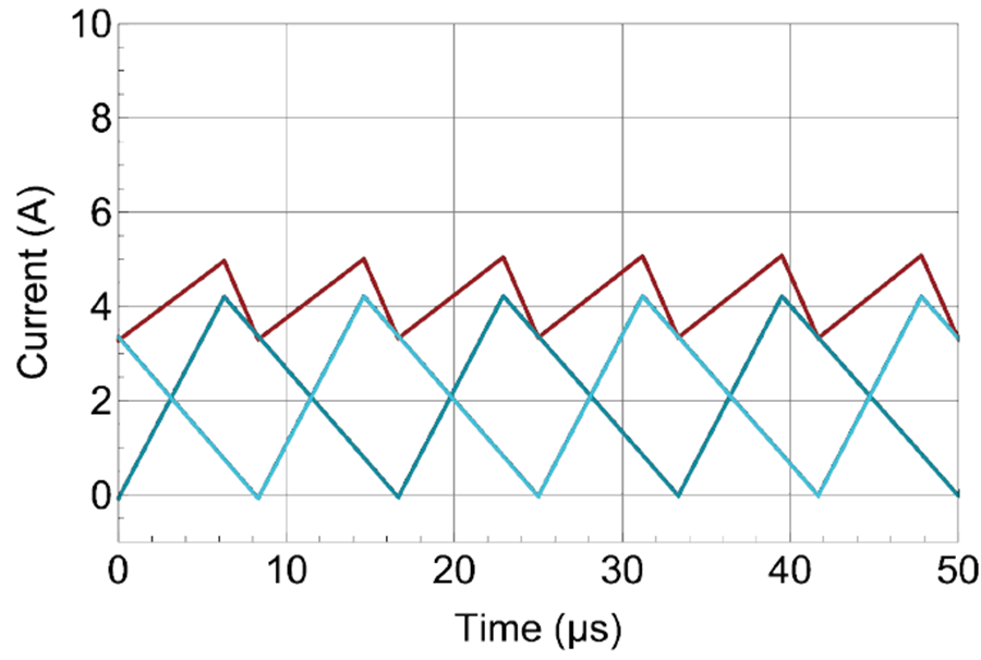 Figure 1-8 Inductor Current (Two Blue) and Total Current (Red) Waveform
While interleaved CrCM and single phase CCM both can be used in the 300 W to 600 W output power range. Table 1-2 show the key differences.
| Design Characteristics | Interleaved CrCM | Single Phase CCM |
|---|---|---|
| Component Stress | Valley switched, less stressful to the power FET | Hard switched, more stressful to the power FET |
| Power Density | Lower | Higher |
| System Height | Smaller (for example, more suitable for slim TV design) | Higher |
| Thermal Management | Easier due to spread over larger space | More challenging in a concentrated area |
| System Cost | More component counts, but less expensive per component | Fewer component counts, but more expensive per component |
TI offers PFC controllers across power range from 75 W all the way to several thousand watts, as shown in #FIG_G3R_XVJ_FWB. In the power range where multiple parts overlap, careful review of the system requirement is needed to provide the best recommendation.
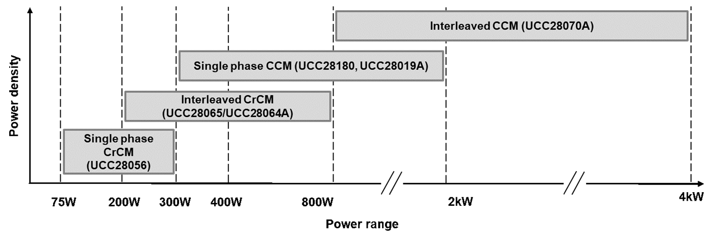 Figure 1-9 Controller Selection Table by the System Power Requirement
For example, in the interleaved CrCM PFC controller family, while UCC28065 offers consistent low iTHD across frequency and inductor value range, UCC28064A offers superior iTHD performance at low switching frequency range, as shown in the #FIG_T1S_NWJ_FWB. Therefore, UCC28065 is more suitable for system that requires smaller form factor design, such as slim TV, while UCC28064A is more suitable for system seeking absolute low iTHD, such as lighting.
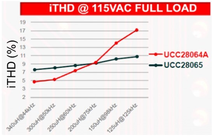 Figure 1-10 iTHD Performance at Low Line, Across Different
Inductor Value and Switching Frequency
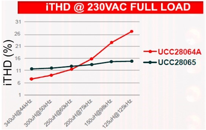 Figure 1-11 iTHD Performance at High
Line, Across Different Inductor Value and Switching Frequency
Figure 1-11 iTHD Performance at High
Line, Across Different Inductor Value and Switching FrequencyTake the single phase CCM PFC family as another example, the feature of programmable switching frequency enables UCC28180 to match with wide variety of power FET, whether it is Si, IGBT, or GaN/SiC. The built-in brown-out protection feature makes UCC28019A more popular in safety critical applications such as server PSU.
Table 1-3 shows the high-level summary of standalone PFC controllers that TI offers. For more product information, please visit the Power Factor Correction controllers homepage.
| GPN | Operation Mode | Phase | Soft Current Limit | Open Loop Detection | Output Under Voltage Protection | Brownout Protection | Over Temp Protection | Ext Clock Sync | Noise Reduction | Idle Current | Switching Frequency | Package |
|---|---|---|---|---|---|---|---|---|---|---|---|---|
| UCC28056 | CrCM | Single | Yes | Yes | Yes | <45uA | 54kHz | SOT23-6 | ||||
| UCC28064A | CrCM | Interleaved | Yes | Yes | Yes | Yes | <200uA | 400kHz | SOIC-16 | |||
| UCC28065 | CrCM | Interleaved | Yes | Yes | Yes | Yes | <200uA | 800kHz | SOIC-16 | |||
| UCC28019A | CCM | Single | Yes | Yes | Yes | <200uA | 65kHz | SOIC-8 | ||||
| UCC28180 | CCM | Single | Yes | Yes | Yes | <75uA | 18-150kHz | SOIC-8 | ||||
| UCC28070A | CCM | Interleaved | Yes | Yes | Yes | Yes | <200uA | 30-300kHz | SOIC/SOP-20 |
IMPORTANT NOTICE AND DISCLAIMER
TI PROVIDES TECHNICAL AND RELIABILITY DATA (INCLUDING DATASHEETS), DESIGN RESOURCES (INCLUDING REFERENCE DESIGNS), APPLICATION OR OTHER DESIGN ADVICE, WEB TOOLS, SAFETY INFORMATION, AND OTHER RESOURCES “AS IS” AND WITH ALL FAULTS, AND DISCLAIMS ALL WARRANTIES, EXPRESS AND IMPLIED, INCLUDING WITHOUT LIMITATION ANY IMPLIED WARRANTIES OF MERCHANTABILITY, FITNESS FOR A PARTICULAR PURPOSE OR NON-INFRINGEMENT OF THIRD PARTY INTELLECTUAL PROPERTY RIGHTS.
These resources are intended for skilled developers designing with TI products. You are solely responsible for (1) selecting the appropriate TI products for your application, (2) designing, validating and testing your application, and (3) ensuring your application meets applicable standards, and any other safety, security, or other requirements. These resources are subject to change without notice. TI grants you permission to use these resources only for development of an application that uses the TI products described in the resource. Other reproduction and display of these resources is prohibited. No license is granted to any other TI intellectual property right or to any third party intellectual property right. TI disclaims responsibility for, and you will fully indemnify TI and its representatives against, any claims, damages, costs, losses, and liabilities arising out of your use of these resources.
TI’s products are provided subject to TI’s Terms of Sale (www.ti.com/legal/termsofsale.html) or other applicable terms available either on ti.com or provided in conjunction with such TI products. TI’s provision of these resources does not expand or otherwise alter TI’s applicable warranties or warranty disclaimers for TI products.
Mailing Address: Texas Instruments, Post Office Box 655303, Dallas, Texas 75265
Copyright © 2023, Texas Instruments Incorporated