-
Inductive Sensing: WEBENCH® Coil Designer Now Designs Stacked Coils for Switch Applications
Inductive Sensing: WEBENCH® Coil Designer Now Designs Stacked Coils for Switch Applications
Ben Kasemsadeh
In my last post, I showed step by step how WEBENCH® Coil Designer can produce the sensor computer-aided design (CAD) files for inductive-sensing applications. This method works well for single-coil inductive sensors such as the LDC1614, but the LDC0851 inductive switch requires two sensors, which can either be side by side or stacked.
With the most recent WEBENCH updates, it is no longer necessary to draw coils by hand; WEBENCH Coil Designer produces coil designs in less than five minutes. Today, I will show you how to design stacked coils in the WEBENCH tool.
What Is the Difference between Stacked and Side-by-side Coils?
A side-by-side arrangement, as shown in Figure 1, enables the greatest sensitivity and is easily implemented for a two-layer printed circuit board (PCB). Exporting two identical coils from the WEBENCH tool and connecting them on one PCB is a sufficient side-by-side coil implementation.
An alternative arrangement is the stacked-coil arrangement, in which the coils are stacked on top of each other on a four-layer PCB. Placing the sense coil on top ensures that the influence of the target on the sense-coil inductance is always stronger than on the reference-coil inductance. This approach is commonly used for space-constrained proximity-sensing applications such as door open/close detection.
 Figure 1 Side-by-side Coil Arrangement (Left) vs. Stacked Coil Arrangement (Right)
How Do I Use WEBENCH Coil Designer to Design Stacked Coils?
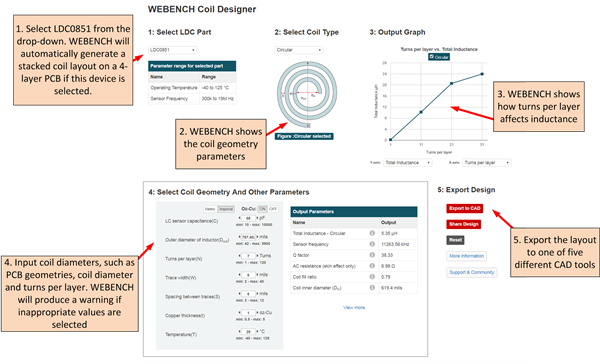
To design a stacked coil with WEBENCH Coil Designer, follow the five steps shown in Figure 2.
 Figure 2 Five Steps for Designing a Stacked Coil in WEBENCH Coil Designer
You can export the coil to any of these CAD formats:
- Altium Designer.
- Cadence Allegro 16.0-16.6.
- CadSoft EAGLE PCB (v6.4 or newer).
- DesignSpark PCB.
- Mentor Graphics PADS PCB.
I used the default settings, which represent the coil on the LDC0851 evaluation module. This configuration is particularly good for sensing larger targets. Note that if you are sensing the presence of small targets such as a screw head, you should add more turns so that the coil-fill ratio (dIN/dOUT) is less than 0.3.
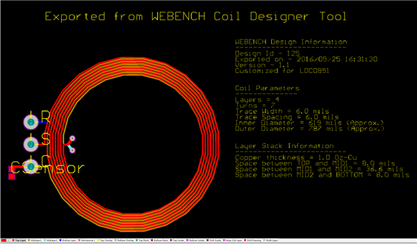
Figure 3 shows the layout in Altium Designer. The Top Layer and MidLayer1 contain the sense coil, while the reference coil spans from MidLayer2 to the Bottom Layer.
 Figure 3 The Finished Coil in Altium Designer Format
Where Is the Switching Point?
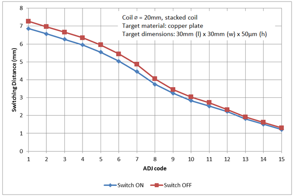
The maximum switching point scales with the coil diameter. You can reduce the switching point down with the ADJ pin to fine-tune the switching distance. For stacked coils, put the LDC0851 in threshold adjust mode. Figure 4 shows the switch-on and switch-off points for a 20mm stacked coil that I designed. The maximum switching distance is about 6.8mm for an ADJ setting of 1 and is scalable down to about 1.2mm for an ADJ setting of 15.
 Figure 4 Threshold Set and Release
Points
Figure 4 Threshold Set and Release
PointsDesigning stacked coils for inductive-switch applications doesn’t need to take much time. By following the approach I’ve described in this post, you can design a coil and export it to the PCB CAD tool of your choice in less than five minutes.
Do you find our WEBENCH tools for inductive sensing useful? Are there other WEBENCH tool features that would make your system design with LDCs easier? If so, leave a note in the comments section below.
Additional Resources
- View the LDC0851 data sheet.
- Download the LDC tools spreadsheet, which includes a dedicated tab to configure an LDC0851.
- Read other blogs about inductive sensing.
IMPORTANT NOTICE AND DISCLAIMER
TI PROVIDES TECHNICAL AND RELIABILITY DATA (INCLUDING DATASHEETS), DESIGN RESOURCES (INCLUDING REFERENCE DESIGNS), APPLICATION OR OTHER DESIGN ADVICE, WEB TOOLS, SAFETY INFORMATION, AND OTHER RESOURCES “AS IS” AND WITH ALL FAULTS, AND DISCLAIMS ALL WARRANTIES, EXPRESS AND IMPLIED, INCLUDING WITHOUT LIMITATION ANY IMPLIED WARRANTIES OF MERCHANTABILITY, FITNESS FOR A PARTICULAR PURPOSE OR NON-INFRINGEMENT OF THIRD PARTY INTELLECTUAL PROPERTY RIGHTS.
These resources are intended for skilled developers designing with TI products. You are solely responsible for (1) selecting the appropriate TI products for your application, (2) designing, validating and testing your application, and (3) ensuring your application meets applicable standards, and any other safety, security, or other requirements. These resources are subject to change without notice. TI grants you permission to use these resources only for development of an application that uses the TI products described in the resource. Other reproduction and display of these resources is prohibited. No license is granted to any other TI intellectual property right or to any third party intellectual property right. TI disclaims responsibility for, and you will fully indemnify TI and its representatives against, any claims, damages, costs, losses, and liabilities arising out of your use of these resources.
TI’s products are provided subject to TI’s Terms of Sale (www.ti.com/legal/termsofsale.html) or other applicable terms available either on ti.com or provided in conjunction with such TI products. TI’s provision of these resources does not expand or otherwise alter TI’s applicable warranties or warranty disclaimers for TI products.
Mailing Address: Texas Instruments, Post Office Box 655303, Dallas, Texas 75265
Copyright © 2023, Texas Instruments Incorporated