-
TPS65132 シングル・インダクタ、デュアル出力電源
- 1 特長
- 2 アプリケーション
- 3 概要
- 4 改訂履歴
- 5 Device Comparison Table
- 6 Pin Configuration and Functions
- 7 Specifications
- 8 Detailed Description
-
9 Application and Implementation
- 9.1 Application Information
- 9.2
Typical Applications
- 9.2.1
Low-current Applications (≤ 40 mA)
- 9.2.1.1 Design Requirements
- 9.2.1.2 Detailed Design Procedure
- 9.2.1.3 Application Curves
- 9.2.2
Mid-current Applications (≤ 80 mA)
- 9.2.2.1 Design Requirements
- 9.2.2.2 Detailed Design Procedure
- 9.2.2.3 Application Curves
- 9.2.3 High-current Applications (≤ 150 mA)
- 9.2.1
Low-current Applications (≤ 40 mA)
- 10Power Supply Recommendations
- 11Layout
- 12デバイスおよびドキュメントのサポート
- 13メカニカル、パッケージ、および注文情報
- 重要なお知らせ
TPS65132 シングル・インダクタ、デュアル出力電源
1 特長
- 入力電圧範囲: 2.5V~5.5V
- VPOS昇圧コンバータ:
4V~6V (0.1Vステップ) - VNEG反転昇降圧型コンバータ:
-6V~-4V (0.1Vステップ) - 最大出力電流:
80mAまたは150mA - 非常に優れた総合効率
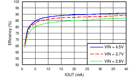
- IOUT > 10mAにおいて85%超
- IOUT > 40mAにおいて90%超
- 優れた性能
- 非常に優れた過渡応答
- 温度範囲の全体にわたって
出力電圧精度1%
- I2Cインターフェイス
- 電源オン/オフのシーケンシング・オプションを
プログラム可能 - 出力電圧を柔軟にプログラム可能
- アクティブ出力放電をプログラム可能
- 1000回以上プログラム可能な不揮発性メモリ
- 電源オン/オフのシーケンシング・オプションを
- 低電圧誤動作防止と過熱保護
- 2つのパッケージ・オプション
- 15ボールCSPパッケージ
- 20ピンQFNパッケージ
2 アプリケーション
- 小型または中型のバイポーラLCDディスプレイ
- スマートフォン、タブレット
- カメラ、GPS
- ホーム・オートメーション、ポイント・オブ・セールス
- ウェアラブル機器(スマートウォッチ、活動量計)
- 汎用分割レール電源
- 差動オーディオ、ヘッドフォン・アンプ
- 計測機器、オペアンプ、コンパレータ
- DAC/ADC
3 概要
TPS65132ファミリは、一般的な正/負駆動アプリケーションに電源を供給するよう設計されています。このデバイスは、両方の出力に単一インダクタのスキーマを使用し、最小のソリューション・サイズ、少ない部品点数、高効率を実現しています。このデバイスは、低ノイズで最高のラインおよび負荷レギュレーションを実現しています。2.5V~5.5Vの入力電圧範囲により、シングル・セル・バッテリ(リチウム・イオン、ニッケル・リチウム、リチウム・ポリマー)で駆動される製品、および3.3Vと5Vの固定電圧レールに対して最適化されています。TPS65132ファミリは、80mAおよび150mAの出力電流オプションがあり、40mAにもプログラム可能です。CSPとQFNの両方のパッケージ・オプションを利用可能です。
製品情報 (1)
| 型番 | パッケージ | 本体サイズ(公称.) |
|---|---|---|
| TPS65132 -B、-L、-T、-S |
DSBGA (15) | 2.11mm×1.51mm |
| TPS65132W | WQFN (20) | 4.00mm×3.00mm |
- 利用可能なすべてのパッケージについては、このデータシートの末尾にある注文情報を参照してください。
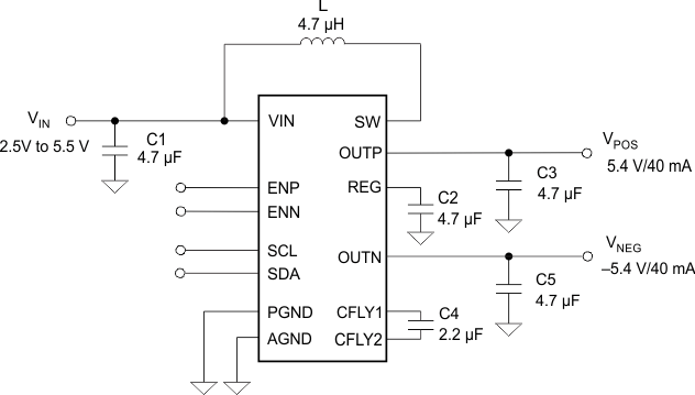
標準アプリケーション

効率 対 出力電流

4 改訂履歴
Changes from G Revision (August 2015) to H Revision
- TPS65132Sから製品プレビューを削除Go
- Changed Device Comparison Table Go
- Added description of clock stretching Go
- Deleted detailed I2C interface description Go
- Added that the DLYx Register is only valid for TPS65132Sx versions. Go
- Changed Table 6 Go
Changes from F Revision (June 2015) to G Revision
- Changed scope figures for Boost Converter switching. Go
Changes from E Revision (November 2014) to F Revision
- Added TPS65132L1 device to Device Comparison table Go
- Added TPS65132T6 device to the Device Comparison Table. Go
- Separated LOGIC SCL, SDA spec MIN/MAX from LOGIC EN, ENN, ENP, SYNC spec MIN/MAXGo
- Changed DAC Registers section for clarity Go
- Added High-current Applications (≤ 150 mA) sectionGo
Changes from D Revision (October 2014) to E Revision
- Added TPS65132L0 device to Device Comparison table Go
Changes from C Revision (July 2014) to D Revision
- 「製品情報」表で、パッケージの種類を業界標準の識別子に変更Go
Changes from B Revision (May 2014) to C Revision
- Added note to Device Comparison Table Go
- Added reference to Power-Down And Discharge (LDO) and Power-Down And Discharge (CPN) Go
- Added Table 1 and various references to itGo
- Added "Power-Down And Discharge (CPN) shows the VNEG discharge behavior of each device variant".Go
- Added Table 2 and various references to it Go
- Added note to Figure 18 Go
Changes from A Revision (August 2013) to B Revision
- 新しいデータシートの標準フォーマットに変更Go
- Added 「製品情報」表に新しいパッケージ・オプション(QFN)をGo
- Added new package option (QFN) to Pin Configurations section Go
- Added the ESD Ratings table Go
Changes from * Revision (June 2013) to A Revision
- Added TPS65132Bx devices to the Device Comparison tableGo
5 Device Comparison Table
| PART NUMBER(1) | PRE-PROGRAMMED OUTPUT VOLTAGES |
IOUT_MAX | PRE-PROGRAMMED IOUT |
PRE-PROGRAMMED ACTIVE DISCHARGE(2) |
STARTUP TIME VPOS / VNEG (4) |
ISD | PACKAGE |
|---|---|---|---|---|---|---|---|
| TPS65132A | VPOS = 5.4 V VNEG = –5.4 V |
80 mA | 40 mA | VPOS / VNEG | FAST | 30 µA | CSP |
| TPS65132A0 | VPOS = 5.0 V VNEG = –5.0 V |
||||||
| TPS65132B | VPOS = 5.4 V VNEG = –5.4V |
80 mA | 40 mA | VPOS / VNEG | FAST | 130 nA | CSP |
| TPS65132B0 | VPOS = 5.0 V VNEG = –5.0 V |
||||||
| TPS65132B5 | VPOS = 5.5 V VNEG = –5.5 V |
||||||
| TPS65132B2 | VPOS = 5.2 V VNEG = –5.2 V |
80 mA | 40 mA | VPOS / VNEG | SLOW | 130 nA | CSP |
| TPS65132L | VPOS = 5.4 V VNEG = –5.4 V |
||||||
| TPS65132L0 | VPOS = 5.0 V VNEG = –5.0 V |
||||||
| TPS65132L1 (3) | VPOS = 5.1 V VNEG = –5.1 V |
80 mA | 40 mA | VPOS / VNEG | SLOW | 130 nA | CSP |
| TPS65132T6 | VPOS = 5.6 V VNEG = –5.6 V |
80 mA | 80 mA | VPOS / VNEG | SLOW | 130 nA | CSP |
| TPS65132S | VPOS = 5.4 V VNEG = –5.4 V |
150 mA | 80 mA | VPOS / VNEG | SLOW | 130 nA | CSP |
| TPS65132W | VPOS = 5.4 V VNEG = –5.4 V |
80 mA | 80 mA | VPOS / VNEG | SLOW | 130 nA | QFN |
6 Pin Configuration and Functions

Pin Functions
| PIN | I/O | DESCRIPTION | ||
|---|---|---|---|---|
| NAME | Ax, Bx, Lx, Tx | Sx | ||
| AGND | D2 | D2 | — | Analog ground |
| CFLY1 | C3 | C3 | I/O | Negative charge pump flying capacitor pin |
| CFLY2 | A3 | A3 | I/O | Negative charge pump flying capacitor pin |
| EN | — | B1 | Enable pin (sequence programmed) | |
| ENN | A1 | — | I | Enable pin for VNEG rail |
| ENP | B1 | B1 | I | Enable pin for VPOS rail |
| OUTP | E3 | E3 | O | Output pin of the LDO (VPOS) |
| OUTN | A2 | A2 | O | Output pin of the negative charge pump (VNEG) |
| PGND | B3 | B3 | — | Power ground |
| E1 | E1 | |||
| REG | D3 | D3 | I/O | Boost converter output pin |
| E2 | E2 | |||
| SCL | B2 | B2 | I/O | I²C interface clock signal pin |
| SDA | C2 | C2 | I/O | I²C interface data signal pin |
| SW | D1 | D1 | I/O | Switch pin of the boost converter |
| SYNC | — | A1 | I | Synchronization pin. 150 mA current enabled if this pin is pulled HIGH. |
| VIN | C1 | C1 | I | Input voltage supply pin |
Pin Functions
| PIN | I/O | DESCRIPTION | |
|---|---|---|---|
| NAME | Wx | ||
| AGND | 3 | — | Analog ground |
| 17 | |||
| CFLY1 | 13 | I/O | Negative charge pump flying capacitor pin |
| CFLY2 | 10 | I/O | Negative charge pump flying capacitor pin |
| ENN | 6 | I | Enable pin for VNEG rail |
| ENP | 5 | I | Enable pin for VPOS rail |
| OUTP | 16 | O | Output pin of the LDO (VPOS) |
| 15 | |||
| OUTN | 9 | O | Output pin of the negative charge pump (VNEG) |
| PGND | 1 | — | Power ground |
| 2 | |||
| 11 | |||
| 12 | |||
| REG | 14 | I/O | Boost converter output pin |
| 18 | |||
| SCL | 8 | I/O | I²C interface clock signal pin |
| SDA | 7 | I/O | I²C interface data signal pin |
| SW | 19 | I/O | Switch pin of the boost converter |
| 20 | |||
| VIN | 4 | I | Input voltage supply pin |
