DLPU100B May 2020 – June 2024 DLP2021-Q1 , DLP3021-Q1
- 1
- Abstract
- Trademarks
- 1Introduction
- 2FPGA Pin Configuration and Functions
- 3Specifications
- 4Feature Descriptions
- 5Layout
- 6Host Command Protocol
- 7FPGA Register Definitions
- 8Revision History
4.3 PWM Outputs
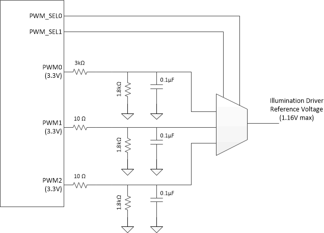
The FPGA has three PWM outputs which typically correspond to red, green, and blue illumination colors. The PWM duty cycles can be adjusted to set a reference voltage to an external illumination driver circuit as needed to balance colors and adjust output brightness.
A typical PWM circuit is shown in Figure 4-1. In this example, each PWM is low-pass filtered and the outputs connect to a 4:1 analog multiplexer. An optional resistor is shown in parallel with the capacitor for each filter to act as a voltage divider if needed to match the required illumination driver reference voltage range. The PWM output frequency is 40 kHz at maximum duty cycle.
The PWM_SELx signals can be used to select which output PWM is multiplexed to the illumination driver while the DMD sequence is executing. Table 4-2 describes the expected relationship between the PWM_SELx outputs and the multiplexer output.
| PWM_SEL0 | PWM_SEL1 | MULTIPLEXER OUTPUT | TYPICAL SEQUENCE COLOR |
|---|---|---|---|
| 0 | 0 | None | None |
| 0 | 1 | PWM1 | Red |
| 1 | 0 | PWM2 | Green |
| 1 | 1 | PWM3 | Blue |
 Figure 4-1 Typical PWM Circuit