DLPU127 December   2023 DLP470NE , DLP480RE , DLP550HE , DLP550JE , DLP650LE , DLP650NE , DLP670RE , DLP780NE , DLP800RE , DLPC4430


  1.   1
  2.   Description
  3.   Get Started
  4.   Features
  5.   Applications
  6.   6
  7. 1Evaluation Module Overview
    1. 1.1 Introduction
    2. 1.2 Kit Contents
    3. 1.3 Specification
    4. 1.4 Device Information
    5. 1.5 Other Items Needed for Operation
  8. 2Software
    1. 2.1 Connecting the DMD EVM to the DLPC4430EVM
    2. 2.2 Quick Start
      1. 2.2.1 Downloading the Software
      2. 2.2.2 Powering-up the DLPC4430EVM and Preparing for the DLPC4430EVM to be Programmed
      3. 2.2.3 Programming the DLPC4430EVM and Displaying a SPLASH Image
      4. 2.2.4 JTAG Flash Programming
      5. 2.2.5 Flash Device Parameters
      6. 2.2.6 Troubleshooting
  9. 3Hardware
    1. 3.1 Connections
      1. 3.1.1 DLPC4430EVM Connections
        1. 3.1.1.1 DLPC4430EVM Connectors
        2. 3.1.1.2 DLPC4430EVM Test Points
      2. 3.1.2 DLP780NEEVM/DLP800REEVM Connections
        1. 3.1.2.1 DLP780NEEVM/DLP800REEVM Connectors
        2. 3.1.2.2 DLP780NEEVM/DLP800REEVM Test Points
      3. 3.1.3 DLP470NEEVM/DLP480REEVM Connections
        1. 3.1.3.1 DLP470NEEVM/DLP480REEVM Connectors
        2. 3.1.3.2 DLP470NEEVM/DLP480REEVM Test Points
      4. 3.1.4 DLP550HEEVM/DLP550JEEVM/DLP650LEEVM Connections
        1. 3.1.4.1 DLP550HEEVM/DLP550JEEVM/DLP650LEEVM Connectors
        2. 3.1.4.2 DLP550HEEVM/DLP550JEEVM/DLP650LEEVM Test Points
      5. 3.1.5 DLP650NEEVM/DLP670REEVM Connections
        1. 3.1.5.1 DLP650NEEVM/DLP670REEVM Connectors
        2. 3.1.5.2 DLP650NEEVM/DLP670REEVM Test Points
    2. 3.2 Power Supply Requirements
      1. 3.2.1 External Power Supply Requirements
  10. 4Hardware Design Files
    1. 4.1 Schematics
    2. 4.2 PCB Layouts
    3. 4.3 Bill of Materials (BOM)
  11. 5Additional Information
    1. 5.1 If You Need Assistance
    2. 5.2 Caution Labels
    3.     Trademarks
  12. 6Related Documentation

Connecting the DMD EVM to the DLPC4430EVM

Before connecting a DLP EVM to the DLPC4420AEVM, identify the male connector on the back of the DMD EVM.

The connectors are keyed by design and must follow an orientation to mate with the female connector (J63) located on the DLPC4430EVM.

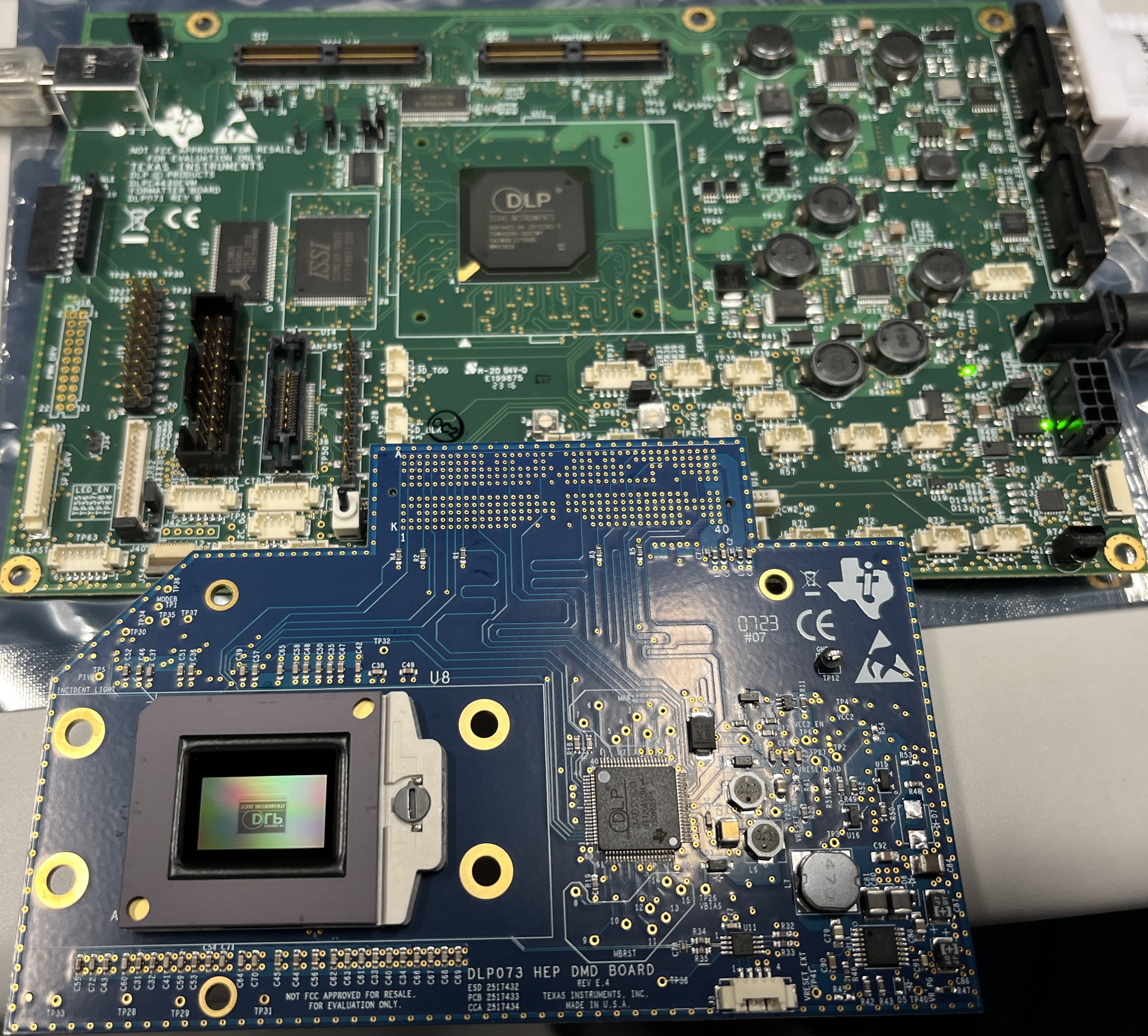
The EVM needs to look like Figure 3-1 after the FMC cables have been properly connected between the DLP650NEEVM and the DLPC4430EVM. The process is the same for use with the other DMDs seen in .
GUID-E957E0CC-1E80-4AEA-A0F7-C6E8644207C2-low.jpgFigure 2-1 EVMs Connected