SBAA483 February 2021 ADS1120 , ADS112C04 , ADS112U04 , ADS114S06 , ADS114S06B , ADS114S08 , ADS114S08B , ADS1220 , ADS122C04 , ADS122U04 , ADS124S06 , ADS124S08 , ADS125H02 , ADS1260 , ADS1261 , ADS1262 , ADS1263
- Abstract
- Trademarks
- 1Introduction
- 2Features Used to Detect Wire Breaks in RTD Systems
- 3Wire-Break Detection Methods for Different RTD Configurations
- 4Settling Time Considerations for RTD Wire-Break Detection
- 5Summary
- A How Integrated PGA Rail Detection Helps Identify Wire Breaks
- B Pseudo-Code for RTD Wire-Break Detection
3.3.2 Detecting Lead 2 and Lead 3 Breaks in a 4-Wire RTD System Using a High-Side RREF
Compared to using a low-side RREF, identifying a break in lead 2 or lead 3 is more difficult in a 4-wire RTD system using a high-side RREF. The main challenge stems from an inability to force current from lead 2 or lead 3 through RREF to trip the VREF monitors. Instead, use a similar diagnostic routine as detailed in Section 3.2.1.1.1. This routine involves the following configuration changes:
- Switch IDAC1 to output on lead 2 (AINP)
- Switch IDAC2 to output on lead 3 (AINN)
- Select the ADC internal VREF as the reference voltage source
- Reduce the PGA gain (if necessary)
- Reduce the IDAC current magnitude (if necessary)
Just as in Section 3.2.1.1.1, the diagnostic cycle requires a different reference source to check the measurement result for a fault because current cannot be forced through RREF in this case. Take care to ensure that the external VREF inputs are reselected when the diagnostic cycle completes.
Also, the last two steps are considered if necessary because the system may already be configured as such before the diagnostic measurement begins. For example, the system may be measuring a large RTD (for example, Pt1000), where the PGA gain is already set to 1 V/V and the IDAC current magnitude is small. These latter two steps are important for fault detection and are described in more detail at the end of Section 3.2.1.1.1.
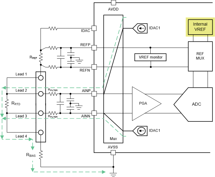
Figure 3-12 shows how to implement the diagnostic measurement for a 4-wire RTD system using a high-side RREF. Lead 4 is assumed to be intact in this case because the VREF monitor is not tripped.
 Figure 3-12 Diagnostic Measurement Checks
if Lead 2 and Lead 3 are Broken in a 4-Wire RTD System Using a High-Side
RREF
Figure 3-12 Diagnostic Measurement Checks
if Lead 2 and Lead 3 are Broken in a 4-Wire RTD System Using a High-Side
RREFDetermine if any faults have occurred by monitoring the conversion result during this diagnostic measurement cycle and interpreting the ADC output as follows:
- If both leads are intact, the conversion result is VIN = VAINP – VAINN = IDAC1 · RRTD, assuming perfectly matched filter resistors. This result is equivalent to just the voltage across the RTD, and is effectively implementing a two-IDAC, 3-wire RTD system that uses the internal voltage reference instead of a ratiometric reference configuration.
- If lead 2 is broken, IDAC1 pulls AINP to AVDD and IDAC2 drives AINN to IDAC2 · (RFILTER + RLEAD3 + RLEAD4 + RBIAS). The resulting output code is a large positive value that is easy to distinguish from the voltage across the RTD.
- If lead 3 is broken, IDAC1 drives AINP to IDAC1 · (RFILTER + RLEAD2 + RRTD + RLEAD4 + RBIAS) and IDAC2 pulls AINN to AVDD. The resulting output code is a large negative value that is easy to distinguish from the voltage across the RTD.
- If both leads are broken, IDAC1 pulls AINP to AVDD and IDAC2 pulls AINN to AVDD as well. With AINP ≈ AINN, the resulting output code is approximately 0, indicating a fault.
See the end of Section 3.2.1.1.1 to understand why a small IDAC current magnitude and reduced PGA gain are required for this diagnostic measurement, as well as guidelines for choosing these values for the system.