SLAAE46 November 2021 DAC43701
3.2 Optimize Power Sequence
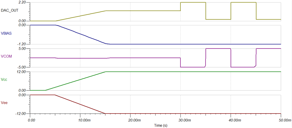
In addition, the common-mode voltage range should be considered to avoid the amplifier working in a nonlinear state. The common-mode voltage of the circuit in Figure 1-2 is 0V, and the common-mode voltage range of the OPA2170 is from (VEE-0.1V) to (VCC-2V). As the bias voltage is divided from VEE, if the VEE supply is applied earlier than VCC, the clipping voltage will be observed at the VCOM output as shown in Figure 3-1, which may cause unexpected flicker.
 Figure 3-1 Transient Simulation Results When VEE Rises up Earlier
To avoid the clipping issue, VCC should power on before VEE, and ensure VCC is greater than 2 V(typical) when VEE powers on, as shown in Figure 3-2.
 Figure 3-2 Transient Simulation Results When VCC Rises up Earlier