SLAAEA3A March 2023 – September 2023 MSPM0G1105 , MSPM0G1106 , MSPM0G1107 , MSPM0G1505 , MSPM0G1506 , MSPM0G1507 , MSPM0G3105 , MSPM0G3106 , MSPM0G3107 , MSPM0G3505 , MSPM0G3506 , MSPM0G3507 , MSPM0L1105 , MSPM0L1106 , MSPM0L1303 , MSPM0L1304 , MSPM0L1305 , MSPM0L1306 , MSPM0L1343 , MSPM0L1344 , MSPM0L1345 , MSPM0L1346
Today, cordless power tools (such as drills, saws, and impact wrenches) and cordless garden tools (such as leaf blowers, string trimmers, and lawn mowers) are smaller, lighter, more efficient, and more powerful due to advancements in battery technology and motor control techniques. All of these cordless tools require a microcontroller (MCU) to control direct current through a motor, and depending on the application, the MCU can also control different operating modes and integrated LEDs. TI’s MSPM0 MCUs can meet these requirements with their high-performance features, broad portfolio, and diverse package sizes.

What are the common components in a power or garden tool design?
Cordless tool-related applications need to control a brushed-DC (BDC) or brushless-DC (BLDC) motor to apply dynamic torque at a constant speed (such as drills and saws), or a constant torque at a dynamic speed (such as blowers). In many designs, the user can adjust the speed of the motor while applying torque to the motor to perform an action, like cutting or drilling wood with a bit, blade, chain, or wheel. For these designs, the main components include:
- Brushed or brushless DC motor: Converts electrical energy into mechanical energy (torque).
- Motor control: PWM logic control signals based on real-time motor position and current feedback, which are translated to driver signals to switch MOSFETs, energize motor windings, and deliver current to commutate the motor.
- Input user interface: Selects torque, direction, or speed of the motor based on buttons, switches, or trigger positions.
- Output user interface: Provides illumination or visual feedback using LEDs or audible feedback using speakers.
- MCU: Leverages integrated digital and analog modules to commutate the motor based on input user interface, communicate with other devices in the system, and provide output user interface for system status.
An application can use TI devices for most of these components that use TI devices for the driver and power stage across a wide range of 3-phase BLDC motor voltages and powers.
| Motor | MCU | Motor Voltage | Predriver | Power Stage, Inverter | Hall Sensor Feedback |
|---|---|---|---|---|---|
| Brushed-DC | MSPM0Lxx Arm Cortex M0+ 32 MHz MCUs or MSPM0Gxx Arm Cortex M0+ 80 MHz MCUs | 5.5 V to 60 V | H-bridge Gate Driver (DRV870x series) | MOSFET (CSD series) | Hall Sensor (DRV5xxx series) |
| 5 V to115 V | H-bridge Gate Driver (DRV877x series) | ||||
| Brushless-DC | 3 V to 40 V | 3-phase BLDC Motor Driver (DRV831x series) | |||
| 4.5 V to 60 V | BLDC Gate Driver (DRV832x series) | MOSFET (CSD series) | |||
| 8 V to 100 V | BLDC Gate Driver (DRV835x series) | ||||
| 5 V to 100 V | BLDC Gate Driver (DRV8300x series) | ||||
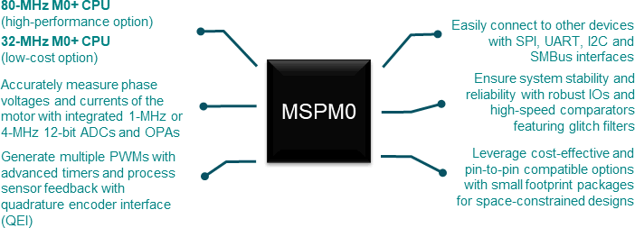
Why is MSPM0 considered for power and garden tool applications?
Texas Instruments' scalable MSPM0 MCU portfolio features an Arm® 32-bit Cortex-M0+ core with a maximum CPU speed of 32-MHz or 80-MHz, depending on the device. The pin-to-pin compatible portfolio covers 4 KB to 512 KB of flash memory with scalable analog integration and motor control modules. With extensive digital, analog, and interface integration, MSPM0 can provide a high-performance and robust option for motor control designs.
What can MSPM0 do in power and garden tool applications?
For basic BDC systems
Most entry-level power tools such as drills, drivers, jigsaws, circular saws, shop vacuums, and even some garden tools like the propulsion system in some electric mowers require a relatively inexpensive low-speed BDC motor.
In this type of system, the MCU performs a simple motor control algorithm to control the motor speed and direction while handling any motor faults. Typically, the MCU also acts as the main processor in the system to control other components such as LEDs or to communicate with other devices such as the battery management system (BMS) in the battery pack. Texas Instruments' 32-MHz MSPM0Lxx series is an option for these types of products.
 Figure 1 MSPM0Lxxx Block Diagram for Brushed-DC Motor Control in Power Tools
Key feature requirements for MCUs in these applications:
- General-purpose timers with complimentary PWM outputs
- 12-bit 1-Msps analog-to-digital converter (ADC)
- 8-bit digital-to-analog converter (DAC)
- Two op-amps with programmable gain (OPAs)
- High-speed comparator (COMP)
- Communication interfaces (UART, I2C, SPI)
- General-purpose inputs and outputs(GPIOs)
Software functions performed on the MCU:
- Control motor speed by generating pulse-width modulation signals (PWMs) based on trigger position and motor current
- Change motor direction based on switch position
- Continuously measure battery voltage and handle any system faults
- Monitor the temperature of the MOSFETs
- Communicate periodically with the battery pack
- Control status or illumination LEDs
For sensored BLDC systems requiring high torque
Many high-performance power tools such as hammer drills and heavy-duty impact wrenches require a BLDC motor to achieve higher power, higher torque, longer lifetime and better efficiency compared to a BDC motor. Sensored BLDC motor applications are typically easier to implement because Hall-effect sensors, Hall elements, or rotary encoders detect the position of the motor regardless of the load conditions, which maintains reliable high-torque start-up and robust operation.
In this type of system, the MCU performs a motor control scheme by generating multiple configurable PWMs in the correct sequence based on feedback from the position sensors and measuring the motor current. Typically, the MCU also acts as the main MCU in the system to control other components such as LEDs or communicate with other devices such as the battery management system in the battery pack or onboard inertial measurement unit (IMU). With a maximum CPU speed of 80 MHz, advanced timers, integrated analog, enhanced communication interfaces, high-drive inputs and outputs (HDIOs), and CAN-FD interface, the MSPM0Gxx series meets these requirements and is a great choice for these types of products.
 Figure 2 MSPM0Gxxx Block Diagram for Sensored BLDC Motor Control in Power Tools
Key feature requirements for MCUs in these applications:
- Advanced timers with complimentary PWM outputs and deadband
- 12-bit 4-Msps ADC
- 12-bit DAC
- Two OPAs with programmable gain
- Two high-speed COMPs
- Communication interfaces (UART, I2C, SPI)
- GPIOs and HDIOs
Software functions performed on the MCU:
- Configure gate driver and diagnose motor faults using optional SPI interface
- Control motor speed by generating PWMs based on trigger position, motor current, and motor position sensors
- Change motor direction or adjust torque output based on switches or buttons
- Continuously measure battery voltage and handle any system faults
- Monitor the temperature of the MOSFETs
- Communicate periodically with the battery pack and other sensors
- Control status or illumination LEDs
For sensorless BLDC systems requiring high speed or small form factor
Outdoor products such as electric mowers, string trimmers, and leaf blowers and also power tools such as low-voltage electric screwdrivers require compact high-speed sensorless BLDC motors. Unlike sensored BLDC motors, these motors do not require position sensors, which saves board space and reduces packaging in designs that require a small form factor. However, sensorless BLDC motors are more challenging to implement than sensored BLDC motors because there are no position sensors to provide motor speed or position data during dynamic load conditions.
In this type of system, the MCU performs an advanced motor control scheme by generating multiple configurable PWMs in the correct sequence based on back electromotive force (BEMF) voltage feedback from the motor. BEMF can be measured using two comparators or calculated using a first-order differential equation (from sampled motor phase voltage and current) to detect when the motor changes states in a six-step commutation pattern. Additionally, a sensorless BLDC system requires a start-up method such as Initial Position Detection (IPD) to determine the position of the motor at rest, an open loop start-up method to not lose motor sync, and a robust hand off to closed-loop control once enough BEMF is detected. Since power tools can spin at high speeds, simultaneously sampling ADC phase voltages and currents at high speeds to minimize latency in the feedback loop is critical.
Furthermore, the MCU can control other components such as LEDs or communicate with other devices such as the battery management device in the battery pack, wireless radios, or other sensors. With a maximum CPU speed of 80-MHz, advanced timers, integrated analog peripherals, enhanced communication interfaces and high-drive inputs and outputs (HDIOs), the MSPM0Gxx series meets these requirements and is an option for these types of products.
 Figure 3 MSPM0Gxxx Block Diagram for Sensorless BLDC Motor Control in Power Tools
Key feature requirements for MCU in these applications:
- Advanced timers with complimentary PWM outputs and deadband
- 12-bit 4-Msps ADC
- 12-bit DAC
- Two OPAs with programmable gain
- Two high-speed COMPs
- Communication interfaces (UART, I2C, SPI)
- GPIOs and HDIOs
Software functions performed on the MCU:
- Configure gate driver and diagnose motor faults using optional SPI
- IPD, align, or slow first cycle startup method
- Open loop to closed loop hand-off with dynamic torque load
- Control motor speed by generating PWMs based on trigger position, motor current and BEMF
- Change motor direction or adjust torque output based on switches or buttons
- Continuously measure battery voltage and handle any system faults
- Monitor the temperature of the MOSFETs
- Communicate periodically with the battery pack, wireless radio or other sensors
- Control status or illumination LEDs
Resources
Order a MSPM0 LaunchPad™ development kit today and a DRV83xxEVM today to start evaluating MSPM0 for a cordless power or garden tool design. Jump-start a design with MSPM0 code examples and interactive online trainings. The following links show resources that are also available:
- MSPM0-SDK
- Designs for MSPM0 motor control
- MSPM0 overview page
- MSPM0 LaunchPad development kits
- LP-MSPM0L1306 LaunchPad development kit
- LP-MSPM0G3507 LaunchPad development kit
- MSPM0 Academy
- DRV83xxEVM
- MSPM0 H-Bridge Control Application Note
- MSPM0 Trapezoidal Control Application Note
- TI Precision Labs - Motor Drivers: Brushless-DC Basics