SLAAEF5 March 2024 MSPM0G1505 , MSPM0G1505 , MSPM0G1506 , MSPM0G1506 , MSPM0G1507 , MSPM0G1507 , MSPM0L1303 , MSPM0L1303 , MSPM0L1304 , MSPM0L1304 , MSPM0L1304-Q1 , MSPM0L1304-Q1 , MSPM0L1305 , MSPM0L1305 , MSPM0L1305-Q1 , MSPM0L1305-Q1 , MSPM0L1306 , MSPM0L1306 , MSPM0L1306-Q1 , MSPM0L1306-Q1
- 1
- Abstract
- Trademarks
- 1Introduction
- 2Algorithm Introduction
- 3Gauge GUI Introduction
- 4MSPM0 Gauge Evaluation Steps
- 5MSPM0 Gauge Solutions
- 6References
5.1.1 Hardware Setup Introduction
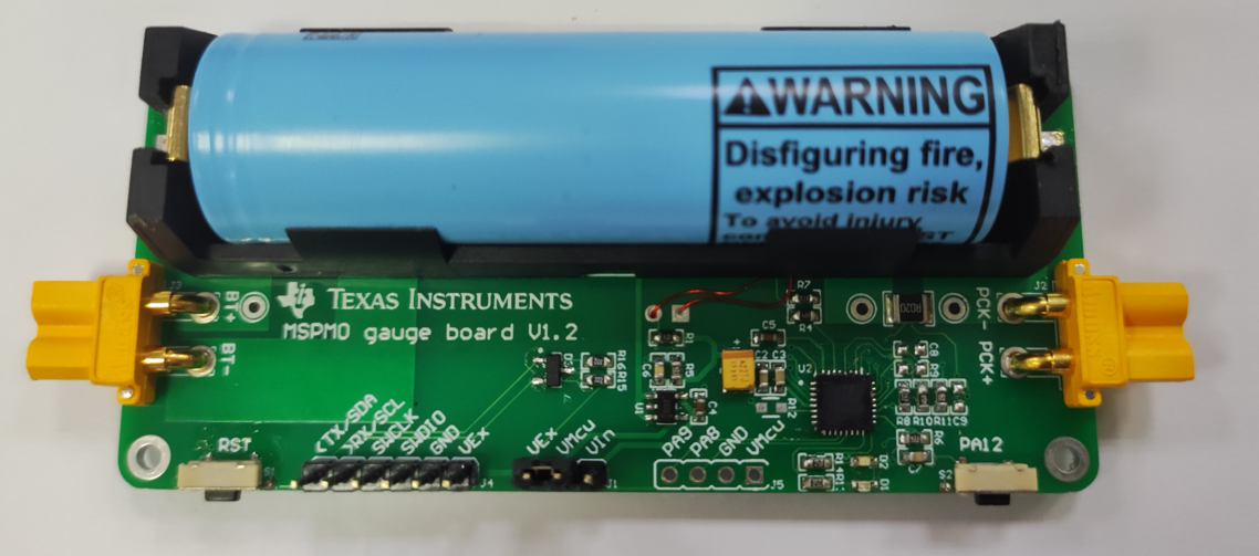
 Figure 5-2 MSPM0 Gauge Hardware Board
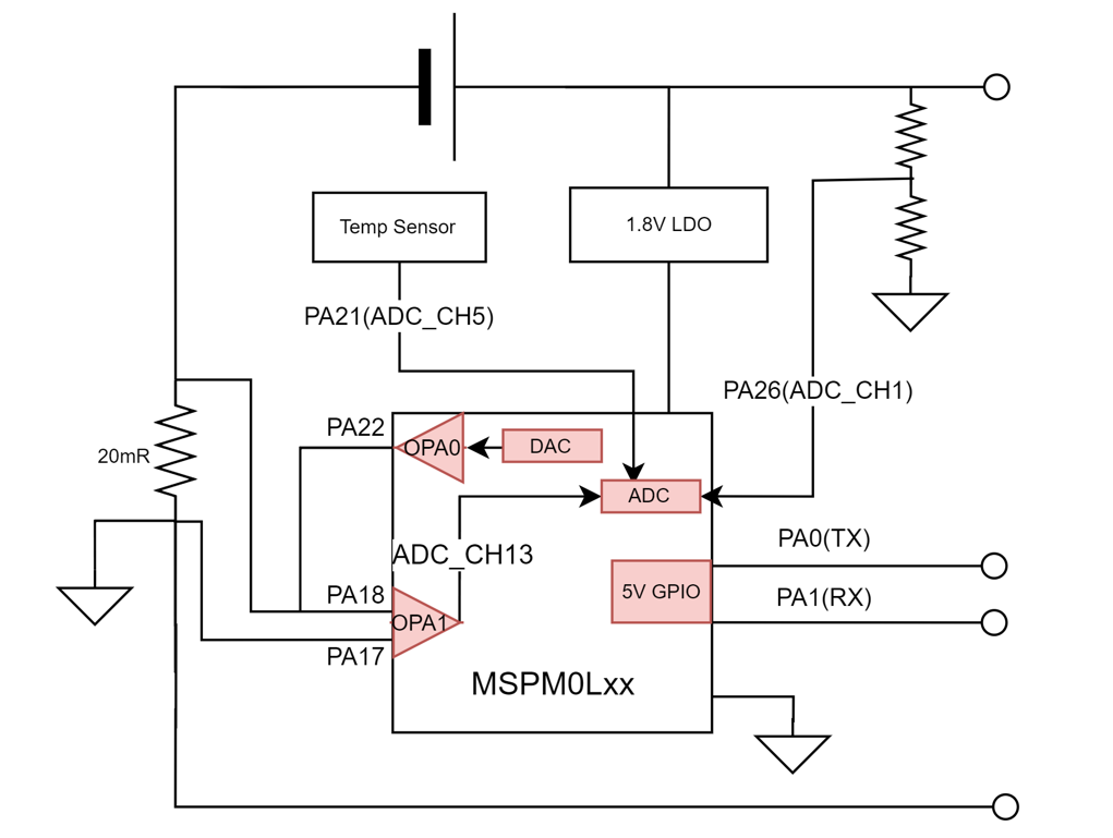
Figure 5-3 shows the hardware high-level block diagram, showing all the used pins by this demo. The solution tests the current at the analog-to-digital controller (ADC) channel 13, the temperature at ADC channel 5 and voltage at ADC channel 1.
 Figure 5-3 MSPM0 Gauge Board Block
Diagram
Figure 5-3 MSPM0 Gauge Board Block
DiagramWith the internal OPA for current detection, its detection error at room temperature can reach ±0.25% at ±2A load. For more hardware introduction and its performance, see A Self-Calibratable Current Detection Solution Based on MSPM0.
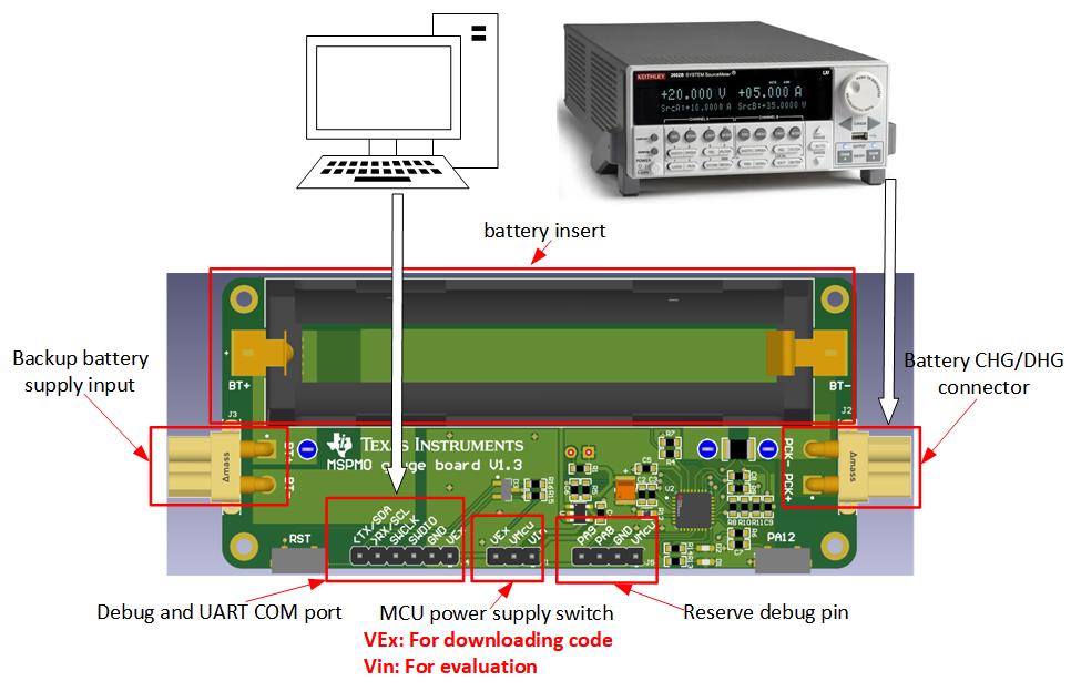
The Gauge board instructions is shown in Figure 5-4. Pay attention to the MCU power switch supply jumper. For downloading, connect VMCU to VEx, then the MCU will be supplied with 3.3V, which can ensure the voltage matching with the debugger. For evaluation, connect VMCU to VIn, then the MCU will be supplied with 1.8V-LDO. It can ensure the best analog performance. Besides, when the MCU is powered in around 500ms, the MCU will calibrate the ADC+OPA for current detection. At this time, the current should be 0. Otherwise, there will be a constant current offset.
 Figure 5-4 Gauge Board Instructions
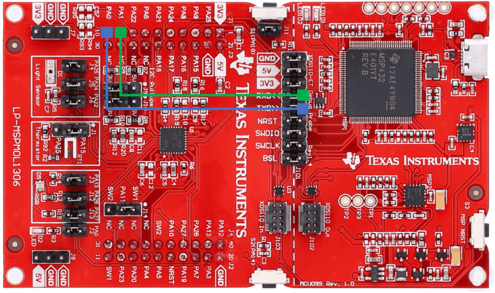
If you use MSPM0L1306 launchpad in communication data input mode, you need to connect the UART pin as follows, besides of doing the software change.
 Figure 5-5 MSPM0L1306 Launchpad UART
Connection