SLAAEF5 March   2024 MSPM0G1505 , MSPM0G1505 , MSPM0G1506 , MSPM0G1506 , MSPM0G1507 , MSPM0G1507 , MSPM0L1303 , MSPM0L1303 , MSPM0L1304 , MSPM0L1304 , MSPM0L1304-Q1 , MSPM0L1304-Q1 , MSPM0L1305 , MSPM0L1305 , MSPM0L1305-Q1 , MSPM0L1305-Q1 , MSPM0L1306 , MSPM0L1306 , MSPM0L1306-Q1 , MSPM0L1306-Q1


  1.   1
  2.   Abstract
  3.   Trademarks
  4. 1Introduction
  5. 2Algorithm Introduction
    1. 2.1 Battery Basic Knowledge Introduction
    2. 2.2 Different SOCs and Used Equations
      1. 2.2.1 NomAbsSoc Calculation
        1. 2.2.1.1 Coulometer With OCV Calibration
        2. 2.2.1.2 Battery Model Filter
      2. 2.2.2 CusRltSoc Calculation
      3. 2.2.3 SmoothRltSoc Calculation
    3. 2.3 Algorithm Overview
      1. 2.3.1 Voltage Gauge Introduction
      2. 2.3.2 Current Gauge Introduction
      3. 2.3.3 Capacity Learn Introduction
      4. 2.3.4 Mixing Introduction
  6. 3Gauge GUI Introduction
    1. 3.1 MCU COM Tool
    2. 3.2 SM COM Tool
    3. 3.3 Data Analysis Tool
  7. 4MSPM0 Gauge Evaluation Steps
    1. 4.1 Step1: Hardware Preparation
    2. 4.2 Step2: Get Battery Model
      1. 4.2.1 Battery Test Pattern
      2. 4.2.2 Battery Model Generation
    3. 4.3 Step3: Input Customized Configuration
    4. 4.4 Step4: Evaluation
      1. 4.4.1 Detection Data Input Mode
      2. 4.4.2 Communication Data Input Mode
  8. 5MSPM0 Gauge Solutions
    1. 5.1 MSPM0L1306 + 1 LiCO2 Battery
      1. 5.1.1 Hardware Setup Introduction
      2. 5.1.2 Software and Evaluation Introduction
      3. 5.1.3 Battery Testcases
        1. 5.1.3.1 Performance Test
        2. 5.1.3.2 Current Consumption Test
    2. 5.2 MSPM0G3507 + BQ76952 + 4 LiFePO4 Batteries
      1. 5.2.1 Hardware Setup Introduction
      2. 5.2.2 Software and Evaluation Introduction
      3. 5.2.3 Battery Testcases
        1. 5.2.3.1 Performance Test1 (Pulse Discharge)
        2. 5.2.3.2 Performance Test2 (Load Change)
  9. 6References

Hardware Setup Introduction

The hardware board is build up based on MSPM0G3507 Launchpad and BQ76952EVM.

MSPM0G3507 LP + BQ76952EVM

GUID-62153672-264A-4B51-9EAD-933463D6F043-low.png

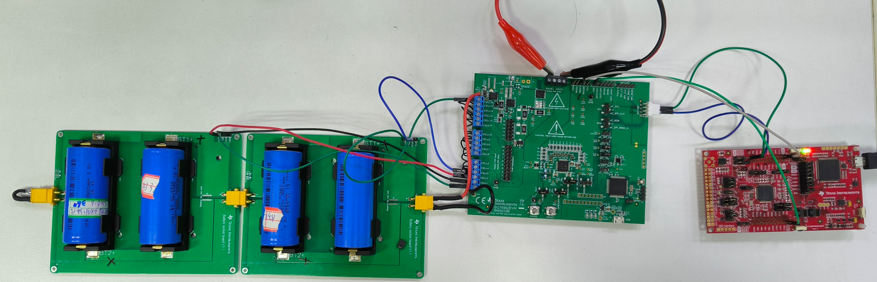
The hardware connection can refer to Figure 5-11. You only need to connect power and I2C between MSPM0 launchpad (SDA: PB3, SCL: PB2)and BQ76952EVM (SDA: J17 PIN3, SCL:J17:PIN2). Rememeber to remove the cell simulation jumpers and add jumpers for I2C pullup.

GUID-325DF3CF-42CC-49A8-A33C-C3F8C59681E4-low.pngFigure 5-11 MSPM0G3507+BQ75952EVM Block Diagram

If you want to use MSPM0G3507 launchpad in communication data input mode, no other hardware change is needed compared with default MSPM0G3507 launchpad hardware set.