SLAAEF5 March 2024 MSPM0G1505 , MSPM0G1505 , MSPM0G1506 , MSPM0G1506 , MSPM0G1507 , MSPM0G1507 , MSPM0L1303 , MSPM0L1303 , MSPM0L1304 , MSPM0L1304 , MSPM0L1304-Q1 , MSPM0L1304-Q1 , MSPM0L1305 , MSPM0L1305 , MSPM0L1305-Q1 , MSPM0L1305-Q1 , MSPM0L1306 , MSPM0L1306 , MSPM0L1306-Q1 , MSPM0L1306-Q1
- 1
- Abstract
- Trademarks
- 1Introduction
- 2Algorithm Introduction
- 3Gauge GUI Introduction
- 4MSPM0 Gauge Evaluation Steps
- 5MSPM0 Gauge Solutions
- 6References
3 Gauge GUI Introduction
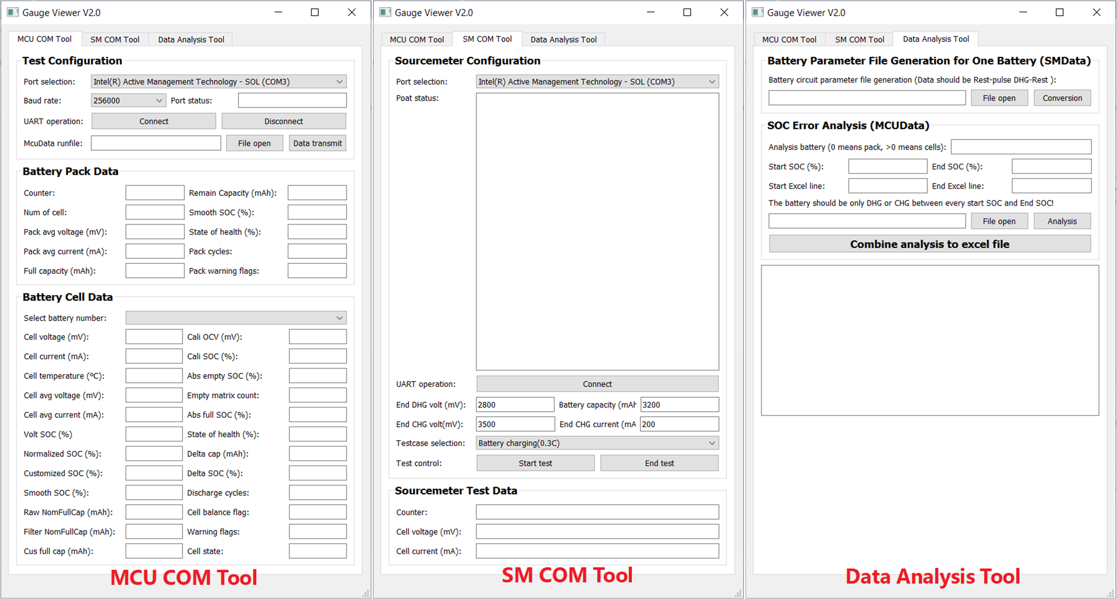
Gauge GUI is also a important part of this solution, shown in Figure 3-1. It can be used to record MCU data, run battery test case, and do data conversion. This GUI has three pages.
- First is MCU COM Tool, used to communicate with MSPM0 and record the MCU transmitted battery running data.
- Second is SM COM Tool, used to communicate with the source meter, run battery test case and record the test data sent from the source meter.
- Third is Data Analysis Tool, used to generate battery parameters and evaluate the SOC error.
Pay attention if you are using GUI excuting file to evaluate the solution, the GUI start up time will be a little long, like 2-3 minutes due to the python language limitation. Instead, using GUI source file will have a faster GUI start up speed.
 Figure 3-1 Guage GUI Functions
A Gauge GUI execution file is supplied. The first open will be very long, like 5 to approximately 10 minutes. You can use it for evaluation without installing python. However, if you want to customize the battery test cases under the SM COM Tool, it is recommended that you to use the source code. For more details about how to use the GUI, see the next sections.