SLAAEF5 March 2024 MSPM0G1505 , MSPM0G1505 , MSPM0G1506 , MSPM0G1506 , MSPM0G1507 , MSPM0G1507 , MSPM0L1303 , MSPM0L1303 , MSPM0L1304 , MSPM0L1304 , MSPM0L1304-Q1 , MSPM0L1304-Q1 , MSPM0L1305 , MSPM0L1305 , MSPM0L1305-Q1 , MSPM0L1305-Q1 , MSPM0L1306 , MSPM0L1306 , MSPM0L1306-Q1 , MSPM0L1306-Q1
- 1
- Abstract
- Trademarks
- 1Introduction
- 2Algorithm Introduction
- 3Gauge GUI Introduction
- 4MSPM0 Gauge Evaluation Steps
- 5MSPM0 Gauge Solutions
- 6References
5.1.2 Software and Evaluation Introduction
Before starting software development and evaluation, it is suggested that you first refer to MSPM0 Design Flow Guide to have a basic understanding about MSPM0 ecosystem. It will help you quickly catch up the MSPM0 development.
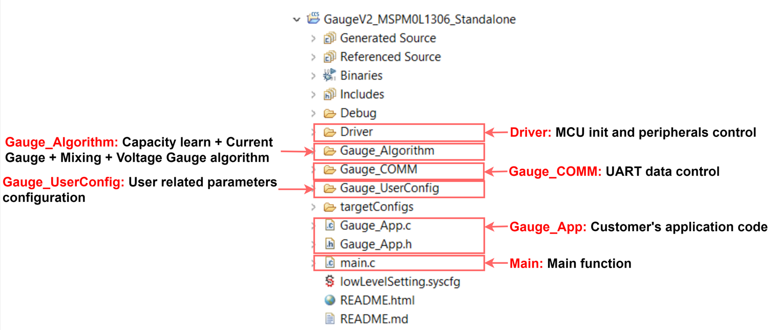
Figure 5-6 illustrates the software project. The project and files related to the gauge algorithm has five parts. For other files, they are same for all the MSPM0 projects.
 Figure 5-6 MSPM0 Gauge Software Project
View
Figure 5-6 MSPM0 Gauge Software Project
ViewFor Gauge_UserConfig part, you will find the description in Section 4.3. The Gauge_Algorithm part introduction is in Section 2. For the Driver part, it includes all the MCU related control. It prepares Icell, Vcell and Tcell data into Gauge_Algorithm. For the Gauge_COMM part, it handles all the UART protocol. For the Gauge_App part, it includes the high-level gauge algorithm calling. This is the place for customers to customize their own functions. For the Main part, it includes the highest system function code.
Remember to follow Section 4 to update the configurations in Gauge_UserConfig folder:
- Generate battery models or use the default one
- Update the configuration in tBattParamsConfig structure
- Update battGlobalParams_xx, and battGlobalParamsArray according to your own battery cells.
- Update the detection mode, communication mode, circuit table length and cell numbers
After you program the MSPM0 through XDS110, you can use the GUI to check and record the results.