SLAAEI9 December 2023 MSPM0C1103 , MSPM0C1103-Q1 , MSPM0C1104 , MSPM0C1104-Q1 , MSPM0G1105 , MSPM0G1106 , MSPM0G1107 , MSPM0G1505 , MSPM0G1506 , MSPM0G1507 , MSPM0G3105 , MSPM0G3105-Q1 , MSPM0G3106 , MSPM0G3106-Q1 , MSPM0G3107 , MSPM0G3107-Q1 , MSPM0G3505 , MSPM0G3505-Q1 , MSPM0G3506 , MSPM0G3506-Q1 , MSPM0G3507 , MSPM0G3507-Q1 , MSPM0G3519 , MSPM0L1105 , MSPM0L1106 , MSPM0L1227 , MSPM0L1228
- 1
- Abstract
- Trademarks
- 1MSPM0 Portfolio Overview
-
2Ecosystem And Migration
- 2.1 Ecosystem Comparison
- 2.2 Migration Process
- 2.3 Example
- 3Core Architecture Comparison
- 4Digital Peripheral Comparison
- 5Analog Peripheral Comparison
2.2.4 Step 4. Software Evaluation
Here are some simple steps to port the example into CCS.
- Select Project, and then import CCS
Projects from the menu.
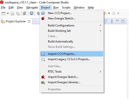 Figure 2-28 Import CCS Projects
 - Choose the
program from SDK. Take the MSPM0L1306, for example.
\mspm0_sdk_1_10_00_05\examples\nortos\LP_MSPM0L1306\driverlib
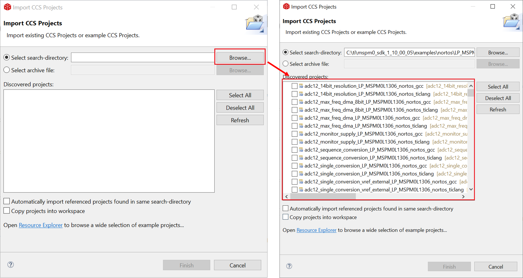 Figure 2-29 Choose Program From SDK
If the file cannot be imported, delete the same name project under workspace.
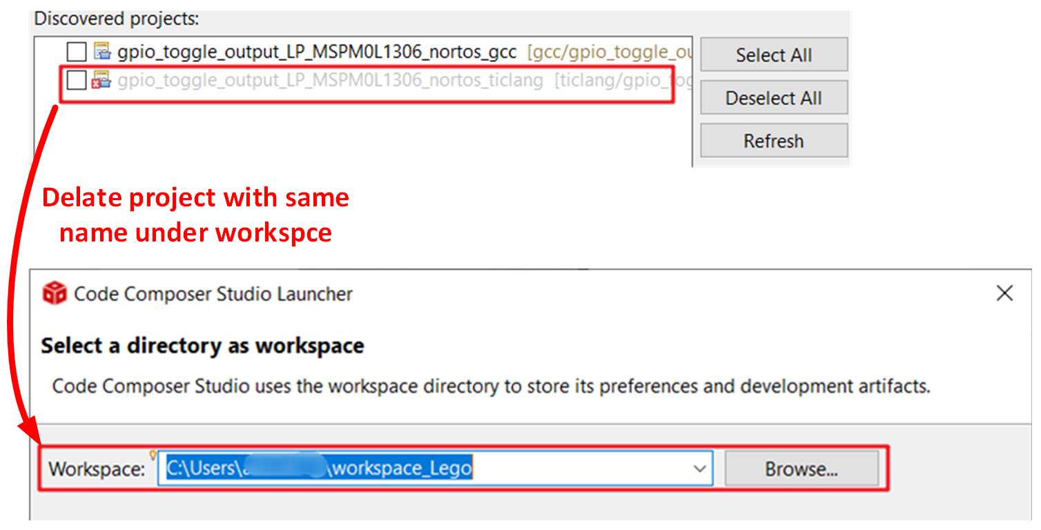 Figure 2-30 Remove Duplicated Project
 - After
importation, there is going be a project lying on the left, and a REAME.md will
automatically open. It is recommended that you read the README.md file first, which
contains the purpose of this example and the hardware configuration.
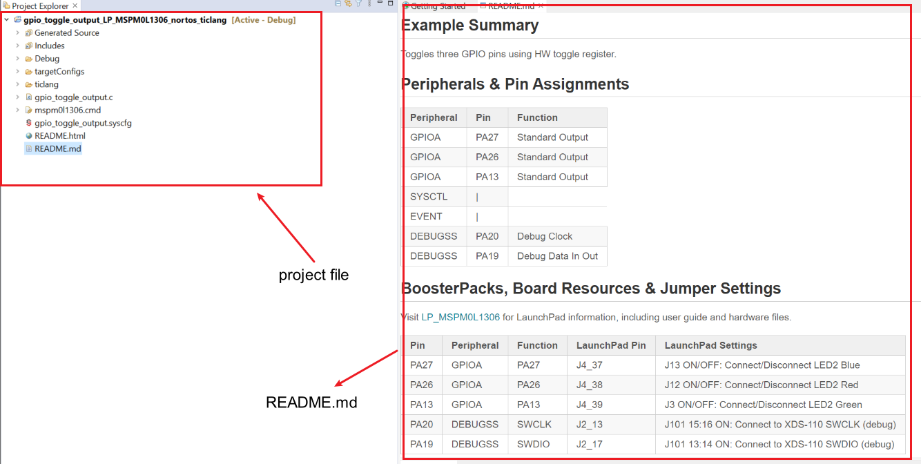 Figure 2-31 Project and README.md
 - Figure 2-32 shows the most important files in the project.
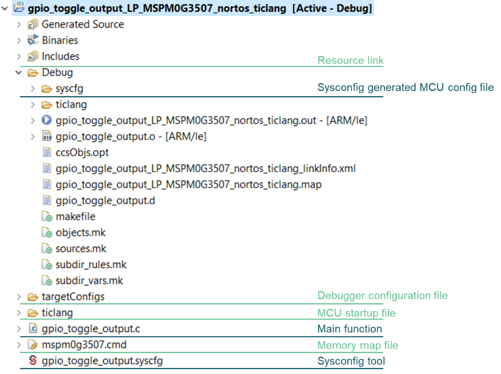 Figure 2-32 CCS Project Overview
 - Just like STM development, TI also supports chip view. Double click .syscfg file, you can reach to SysConfig, where you are allowed to configure the required peripherals through a graphical interface. And, it is suggested to use the MCU view of SysConfig to help you fix the pin function first with software engineer, which is similar to MCU/MPU Package in STM8CubeMAX.
- Based on the code and SysConfig example, you are able to polish the project or modify them with device-specific TRM or application note released on Ti.com.
- If you want to add third-party libraries,
you can follow the steps below. First, you have to add relevant file into your project, as
shown in Figure 2-33.
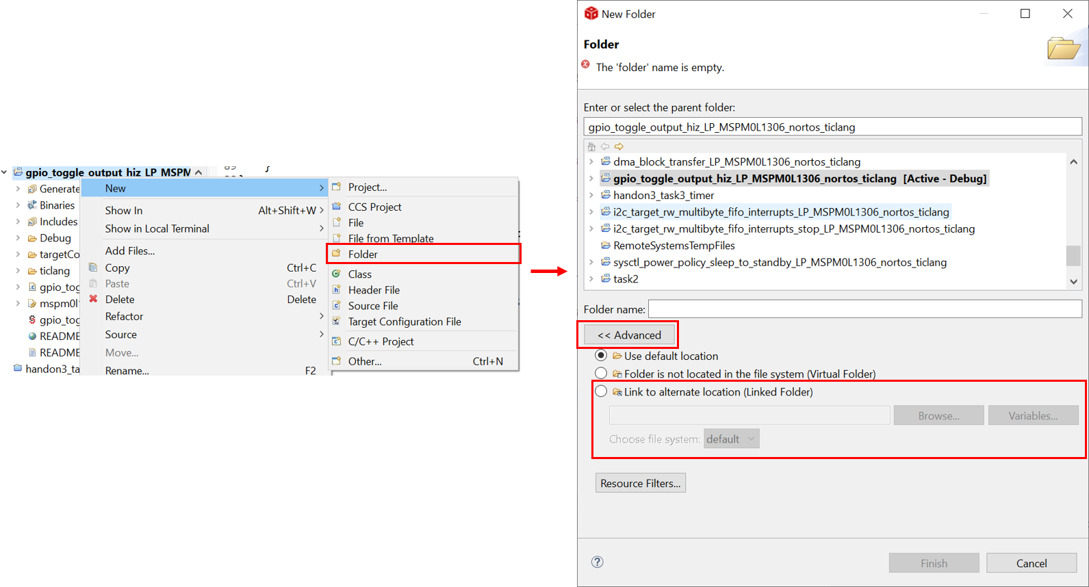 Figure 2-33 Add Relevant File
Then, other steps need to be done in order to tell compiler that you have add header files.
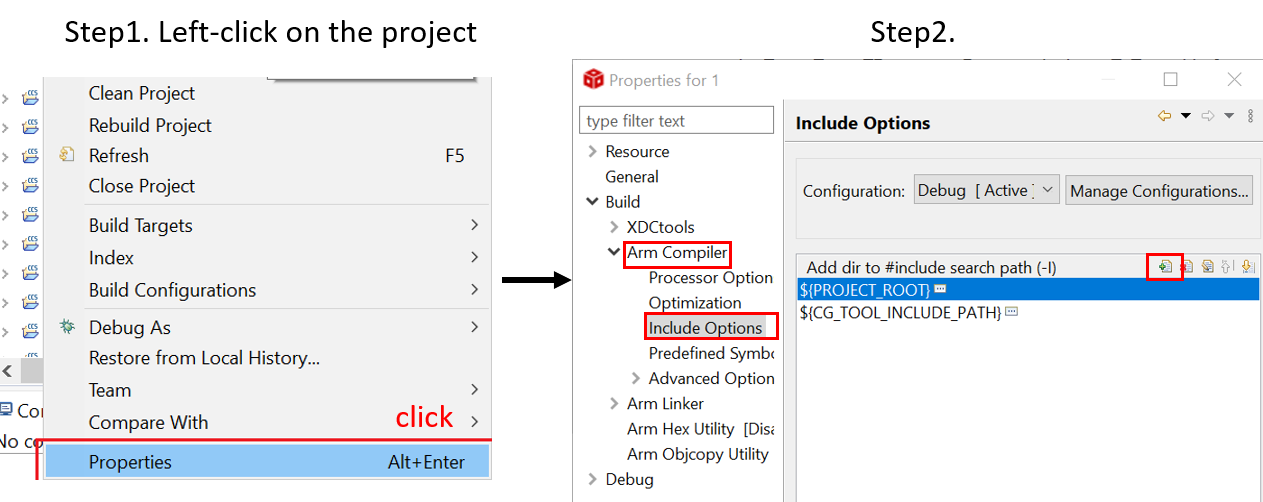 Figure 2-34 Include Options Set
 - As you finish evaluating the software,
click “build” icon in the main toolbar, as shown in Figure 2-35. The appearance of “Build Finished” shows your successful compilation.
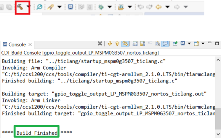 Figure 2-35 Successful Build