SLAAEI9 December 2023 MSPM0C1103 , MSPM0C1103-Q1 , MSPM0C1104 , MSPM0C1104-Q1 , MSPM0G1105 , MSPM0G1106 , MSPM0G1107 , MSPM0G1505 , MSPM0G1506 , MSPM0G1507 , MSPM0G1519 , MSPM0G3105 , MSPM0G3105-Q1 , MSPM0G3106 , MSPM0G3106-Q1 , MSPM0G3107 , MSPM0G3107-Q1 , MSPM0G3505 , MSPM0G3505-Q1 , MSPM0G3506 , MSPM0G3506-Q1 , MSPM0G3507 , MSPM0G3507-Q1 , MSPM0G3519 , MSPM0L1105 , MSPM0L1106 , MSPM0L1117 , MSPM0L1227 , MSPM0L1228
- 1
- Abstract
- Trademarks
- 1MSPM0 Portfolio Overview
-
2Ecosystem And Migration
- 2.1 Ecosystem Comparison
- 2.2 Migration Process
- 2.3 Example
- 3Core Architecture Comparison
- 4Digital Peripheral Comparison
- 5Analog Peripheral Comparison
2.1.3 SysConfig
Similar to STM8CubeMX, SysConfig is an intuitive and comprehensive collection of graphical utilities for configuring pins, peripherals, radios, subsystems, and other components, which can be seen in Figure 2-3. SysConfig helps manage, expose, and resolve conflicts visually so that you have more time to create differentiated applications. The tool's output includes C header and code files that can be used with MSPM0 SDK examples or used to configure custom software. SysConfig is integrated into CCS but can also be used with Keil and IAR.
SysConfig can be downloaded at the following URL: SYSCONFIG IDE, configuration, compiler or debugger | TI.com.
Besides, SysConfig can run without an IDE. The standalone version can be used for code generation and to evaluate the capabilities of the device, but is not capable of running an example.
 Figure 2-3 MSPM0 SysConfig
Here are the same and different features between SysConfig and STM8CubeMX,
- Both of them allow creating, saving and importing previously saved projects. STM8CubeMX projects comes with an .ioc8 file that can be saved anywhere, next to other .ioc8 files. But STM8CubeMX does not support C code generation, which is different from SysConfig and may extend development time.
- Both of them allow easy pinout and clock tree configuration, which can be seen from Chip view.
- STM8CubeMX support power consumption calculation, which, for MSPM0, can be realized in CCS IDE.
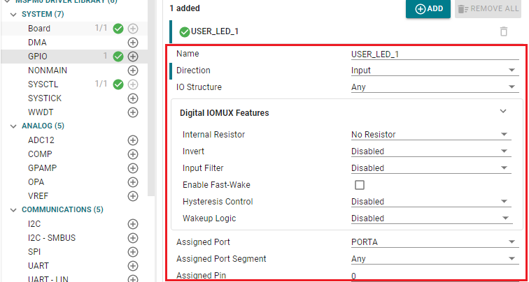
- SysConfig supports more comprehensive configuration capabilities. Different from STM8CubeMX,which can only config pinout or simple configuration for peripheral, SysConfig provides more specific and detailed initialization configurations. As shown in Figure 2-4, SysConfig can configure the type of GPIO as well as features such as internal pull-up/pull-down resistors.
- STM8CubeMX comes with an updater mechanism that can be configured for automatic or on-demand check for updates, which supports STM8CubeMX self-updates. SysConfig doesn't support that and users can download newest version from SysConfig download.
 Figure 2-4 GPIO Configuration in
SysConfig