SLAAEI9 December 2023 MSPM0C1103 , MSPM0C1103-Q1 , MSPM0C1104 , MSPM0C1104-Q1 , MSPM0G1105 , MSPM0G1106 , MSPM0G1107 , MSPM0G1505 , MSPM0G1506 , MSPM0G1507 , MSPM0G1519 , MSPM0G3105 , MSPM0G3105-Q1 , MSPM0G3106 , MSPM0G3106-Q1 , MSPM0G3107 , MSPM0G3107-Q1 , MSPM0G3505 , MSPM0G3505-Q1 , MSPM0G3506 , MSPM0G3506-Q1 , MSPM0G3507 , MSPM0G3507-Q1 , MSPM0G3519 , MSPM0L1105 , MSPM0L1106 , MSPM0L1117 , MSPM0L1227 , MSPM0L1228
- 1
- Abstract
- Trademarks
- 1MSPM0 Portfolio Overview
-
2Ecosystem And Migration
- 2.1 Ecosystem Comparison
- 2.2 Migration Process
- 2.3 Example
- 3Core Architecture Comparison
- 4Digital Peripheral Comparison
- 5Analog Peripheral Comparison
3.6.1.2 Interrupt Controller (ITC) of STM8
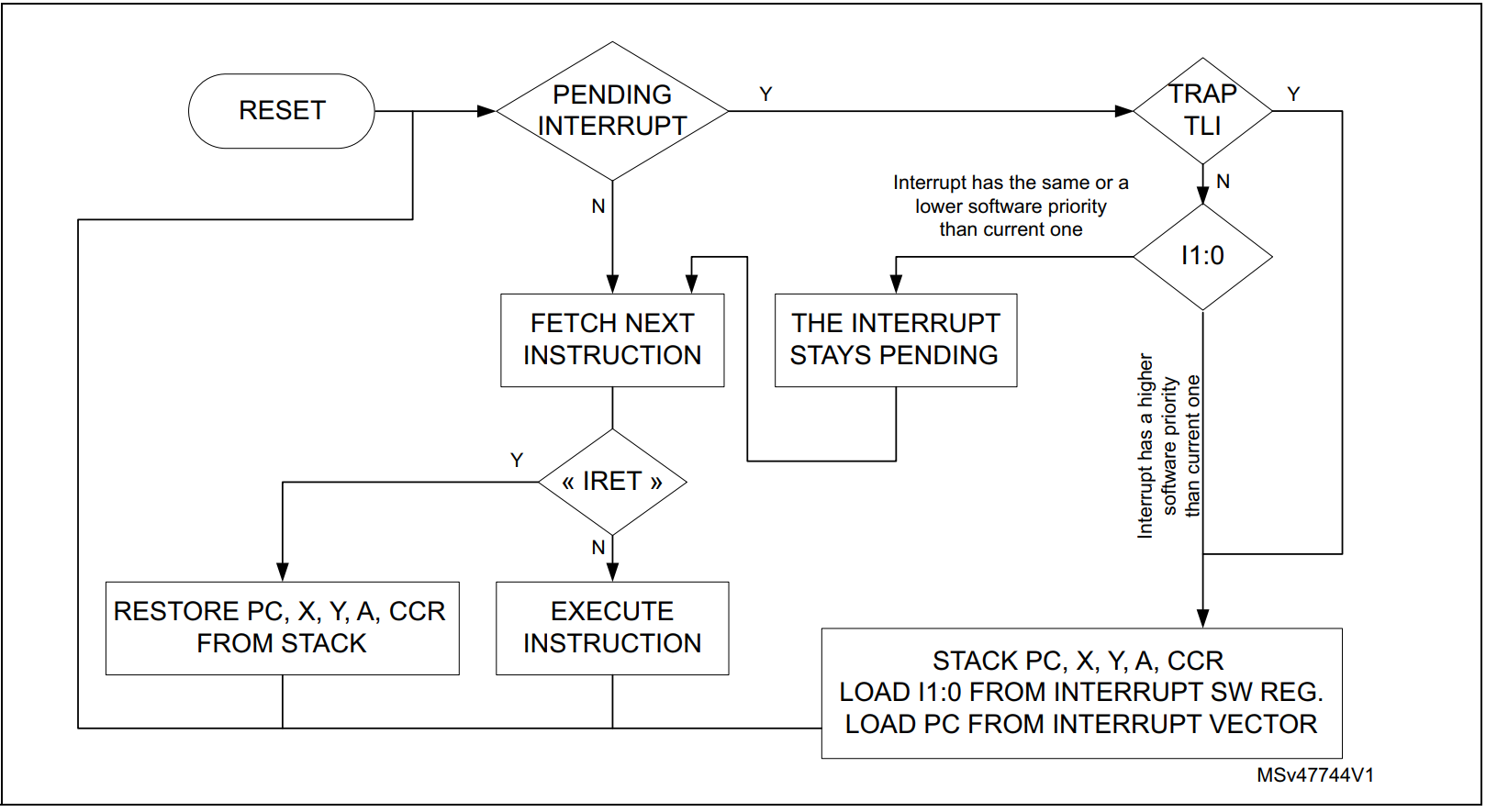
Figure 3-3 shows the interrupt processing flowchart of STM8. If the interrupt mask bits I0 and I1 are set within an interrupt service routine (ISR) with the instruction SIM, removal of the interrupt mask with RIM causes the software priority to be set to level 0.The interrupt service routine need to end with the IRET instruction which causes the content of the saved registers to be recovered from the stack. As a consequence of the IRET instruction, bit I1 and I0 are restored from the stack and the program execution resumes.
 Figure 3-3 Interrupt Processing
Flowchart