SLUAA04A june 2020 – may 2023 BQ25150 , BQ25155 , BQ25618 , BQ25619 , TS5A12301E , TS5A3157 , TS5A3159A , TS5A6542
6.1 Dynamic Voltage Adjustment
The first system shown is the one discussed in this paper. This design offers the best performance as a result of the 2-pin communication-enabled, efficient charging scheme. By reducing the difference between the case output voltage and the earbud battery voltage, the power dissipated by the linear battery charger is reduced. This allows for optimal thermal performance and increased case battery life.
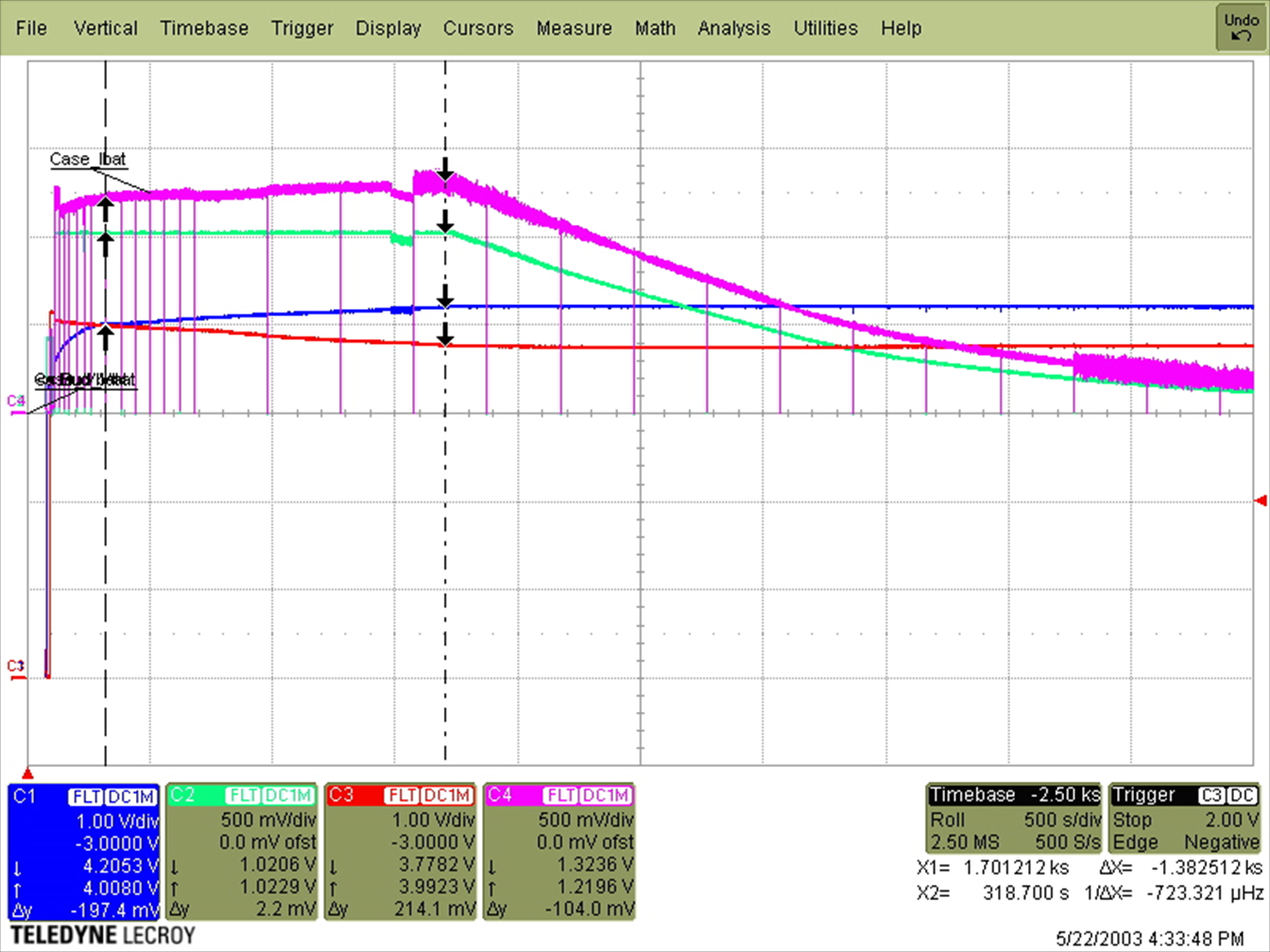
Below is a scope capture of a charging cycle using the proposed solution. The maximum current at the input of the case was 265 mA, while providing 200 mA to the earbud battery. Each pulse that can be seen is a communication cycle.
 Figure 6-1 Charge Cycle of the Dynamic
Voltage Adjustment Design
Figure 6-1 Charge Cycle of the Dynamic
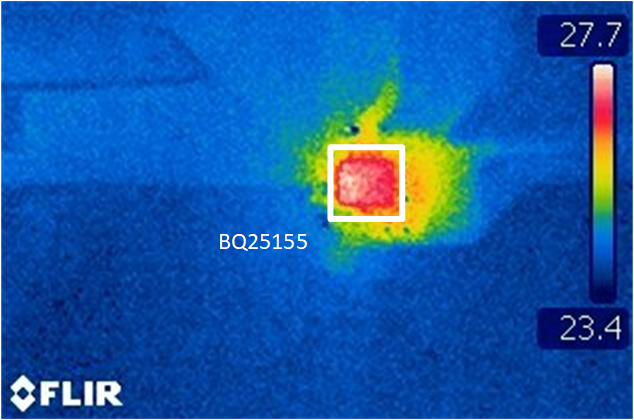
Voltage Adjustment DesignFigure 6-2 shows an image taken by a FLIR thermal camera. This image shows the system at its maximum temperature during the charging process. The temperature of 27.7°C is only 2.7°C above the ambient room temperature of 25°C.
 Figure 6-2 Thermal Performance of the
Dynamic Voltage Adjustment Design