SLUAA04A june 2020 – may 2023 BQ25150 , BQ25155 , BQ25618 , BQ25619 , TS5A12301E , TS5A3157 , TS5A3159A , TS5A6542
3.1 Initialization and Main Code
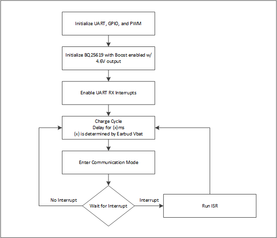
For this communication scheme, the case acts as the master and the earbud acts as the slave. Figure 3-1 is a flow chart of the case algorithm.
 Figure 3-1 Case Algorithm
The case is first initialized to meet the user’s system requirements. Settings here include the output voltage and current of the BQ25619, PWM Frequency, Startup PWM Duty Cycle, UART Initialization, etc. After initialization, the interrupts for the system are enabled. At this point the system is ready to start a charging cycle when the earbuds are inserted.
Upon detection of the earbuds, a charging cycle is started. The case will then output 4.6 V for a user-set time. This is to ensure that the earbud battery is not dead and the device can respond during communication cycles. After the user-set time has elapsed, the case will then initiate a communication cycle by disabling the TPS22910A load switch and enabling the TS5A12301E UART switch. The case will then wait for a UART transmission from the earbud to trigger an interrupt.
These communication cycles occur at user-defined intervals that should be based on the charging curve of the battery. At the beginning of a charge cycle, it can be expected that a discharged battery will be in the range of 3.0 V to 3.7 V. This will depend on how deep the battery has been discharged and the settings the customer has chosen for battery cut-off voltage. At this point, the voltage of the earbud battery will change rapidly so the time between communication intervals needs to be small (~5 sec). As the earbud battery voltage rises the voltage will change at a slower pace allowing for the intervals to be increased, minimizing the time the system needs to be in communication mode.