SLVAFE1 December 2024 DRV8210 , DRV8220 , TLV9061
2 Demo Hardware
The block diagram for the demo smoke alarm setup based on the MSPM0G3507 and DRV8220 is shown in the Figure 2-1. The introduced setup consists of an MSPM0G3507 LaunchPad™ development kit to which two additional TI evaluation boards are connected. Evaluation module TLV61046AEVM-833 is used to provide an appropriate voltage rail for the driver module DRV8220EVM and piezo element. This arrangement supports either a single ended PWM (for alarm tone generation) or a differential PWM (such as BD modulation) to drive the piezo speaker. BD Modulation is used in this demo to accommodate both audio playback and alarm tone generation.
 Figure 2-1 Smoke Alarm Sounder With the DRV8220 and MSPM0G Hardware Block Diagram
The MSPM0G350x family of microcontrollers are ultra-low-power MCU’s which operate with a supply voltage ranging from 1.62V to 3.6V. The LaunchPad™ presented in this demo is powered via USB cable plugged into a PC and provides an input voltage rail of 5V. The MSPM0G3507 LaunchPad includes an LDO which provides the 3.3V rail for powering the MCU and the boost converter input. The DRV8220 H-Bridge features an operating voltage range of 4.5V to 18V. This demo uses the default 12V output from the TLV61046AEVM for the piezo drive voltage, however, this voltage is adjustable on the EVM. The DRV8220 motor driver was chosen for this application because of the low power dissipation and low cost. The H-bridge design in the DRV82xx family is also capable of driving capacitive loads which is also an important consideration in this application.
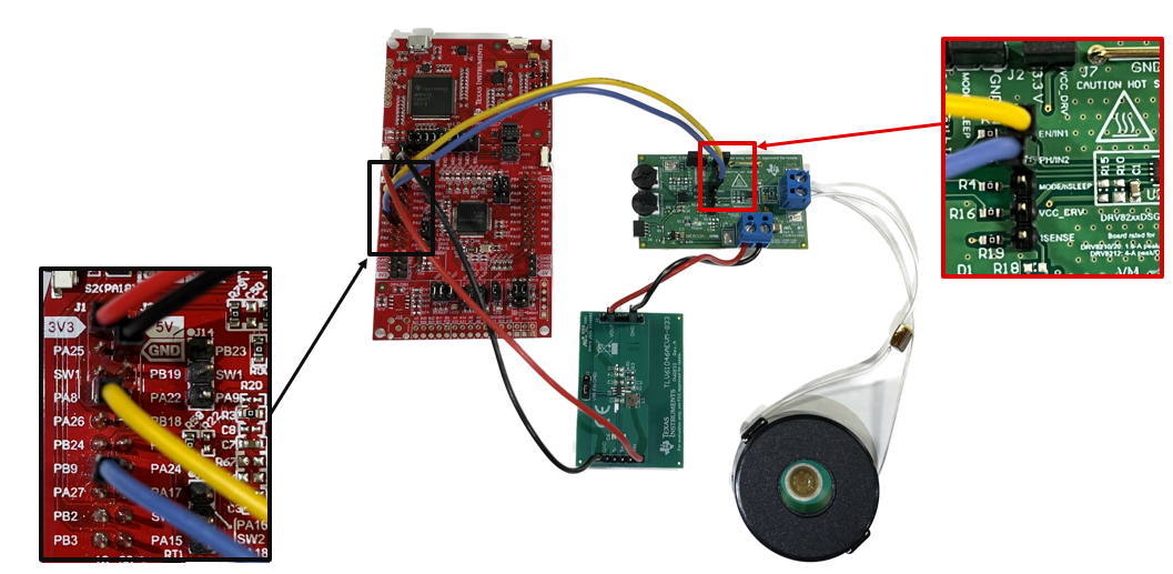
The hardware demo connections are shown in Figure 2-2 and detailed in the following:
- MSPM0G 3.3V is connected to TLV61046A VIN
- MSPM0G GND is connected to TLV61046A GND
- TLV61046A VOUT is connected to DRV8220 VM
- TLV61046A GND is connected to DRV8220 GND
- MSPM0G PA8 is connected to DRV8220 IN1
- MSPM0G PA9 is connected to DRV8220 IN2
- DRV8220 OUT1 is connected to PCT-4546E Piezo
- DRV8220 OUT2 is connected to PCT-4546E Piezo
- USB cable is connected from PC to MSPM0G Launchpad
 Figure 2-2 Hardware Demo Connections
The MSPM0G350x microcontrollers (MCUs) are part of the MSP highly integrated, ultra-low-power 32bit MCU family based on the enhanced Arm® Cortex®-M0+ 32bit core platform operating at up to 80MHz frequency. High-performance integrated analog peripherals simplify the supply chain and optimize the cost. MSPM0G350x integrates two 12bit 4Msps ADCs, configurable internal shared voltage reference, one 12bit 1Msps DAC, three high speed comparators with built-in reference DACs, two zero-drift zero-crossover op-amps with programmable gain, and one general-purpose amplifier. Moreover, the MSPM0G350x incorporates intelligent digital peripherals, such as seven timers which supports up to 22PWM channels. MSPM0 MCU platform combines the Arm Cortex-M0+ platform with a holistic ultra-low-power system architecture, allowing increased performance while reducing energy consumption, which is especially crucial with application as smoke alarm which require more power to produce low frequency tone.
The DRV8220 is an integrated motor driver with four N-channel power FETs, charge pump regulator, and protection circuitry. The triple charge pump architecture allows reduction of design size and 100% duty cycle operation with operating supply voltage range between 4.5V to 18V. The DRV8220 H-Bridge Motor Driver supports multiple control interface modes: PWM, phase/enable, independent half-bridge and parallel half -bridge and within those each supports a low-power sleep mode to make sure ultra-low quiescent current draw. The DRV8220 is part of a family of devices which come in pin-to-pin scalable RDS(on) and supply voltage options to support various loads and supply rails with minimal design changes.
The TLV61046A is a highly-integrated boost converter, that integrates a 30V power switch, an input to output isolation switch, and a rectifier diode. TLV61046A can output up to 28V from input of a Li+ battery or two alkaline batteries in series. TLV61046A implements output short circuit protection, output overvoltage protection, and thermal shutdown. Within this application internal default 12V output voltage setting by connecting the FB pin to the VIN pin is used.
The piezoelectric sounder AT-4625-TT-HT-R used in this hardware demo has a wide range of operating voltage from 3Vp-p to 30Vp-p with a current draw ≤80mA. The minimum SPL is rated at 120/100dBA for 10cm/1m, with the ability to create more than 90dBA output at 3 meters. Perhaps more importantly for this application is that AT-4625-TT-HT-R exhibits a relatively flat response over a wide range of frequencies as opposed to the more typical selective frequency response.