SLVAFT6 September 2024 TPS23521 , TPS23523 , TPS23525
1 Introduction
The input power system of the network equipment is composed of a negative -48V DC bus system for the purpose of the protection against harsh environments such as lighting and moisture, thereby achieving a longer lifespan. The normal operating range is generally between -38V and -58V, but a voltage can exceed the normal operating range during the transient condition or system malfunctions. To address this, over-voltage and under-voltage protection functions are typically applied to the hot-swap controller, which turns off the hot-swap unit if the input power is outside the set range, blocking the power path to the downstream circuitry. A system block diagram of a remote radio unit (RRU) is depicted in Figure 1-1.
 Figure 1-1 Remote Radio Unit System Block Diagram
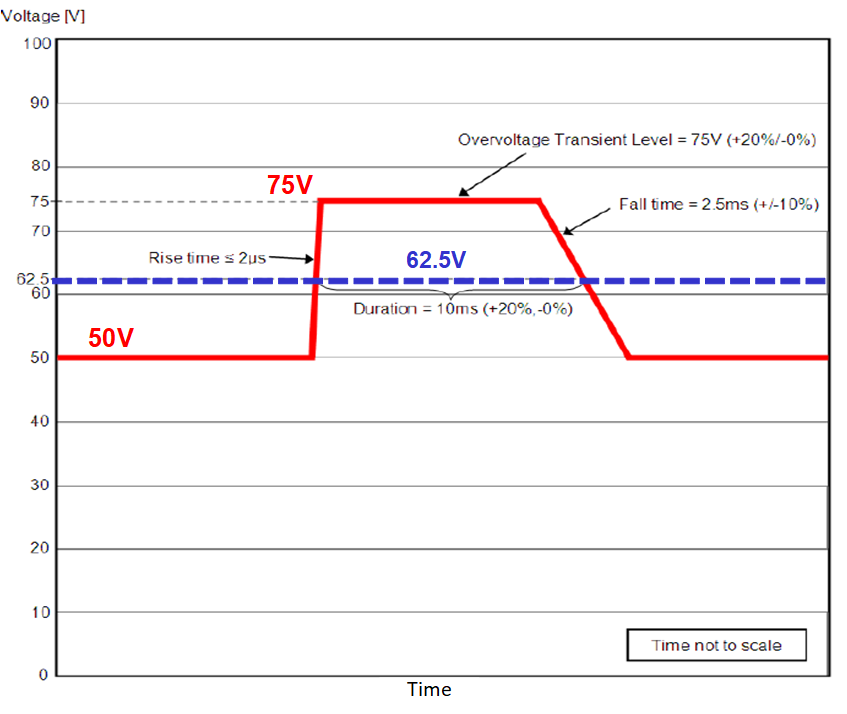
Also, the input voltage range varies depending on the requirements of the operator, and specifically in the case of products aimed at North America, an additional standard for over-voltage transients included in the NEBS (Network Equipment-Building System) specification must be met. The over-voltage standard indicates excessive conditions and noise characteristics outside the normal operating range of the input power device, including an applied input voltage level of 75V (+20%/-0%) for 10ms (+20%/-0%), as shown in the profile in Figure 1-2, in the worst case. Meanwhile, this requires the network equipment to remain in normal operation without a power outage. If the hot-swap is maintained in ON state, the high input voltage of the system determines the voltage rating of the downstream DC-DCs in Figure 1-1, which increases the system cost. Therefore, the recommendation is to limit the output over-voltage resulting in a compact and cost-optimized design with low-voltage downstream components.
 Figure 1-2 Transient Input Voltage Profile as per NEBS, ATIS-0600315.2018 Standard