SLVUBT8B November 2020 – June 2022 LP8764-Q1 , TPS6594-Q1
- Scalable PMIC's GUI User’s Guide
- Trademarks
- 1 Introduction
- 2 Supported Features
- 3 Revisions
- 4 Overview
- 5 Getting Started
- 6 Quick-start Page
- 7 Register Map Page
- 8 NVM Configuration Page
- 9 NVM Validation Page
- 10Watchdog Page
- 11Additional Resources
- 12Appendix A: Troubleshooting
- 13Appendix B: Advanced Topics
- 14Appendix C: Known Limitations
- 15Appendix D: Migration Topics
- 16Revision History
8.1.2.1 Creating a State Diagram
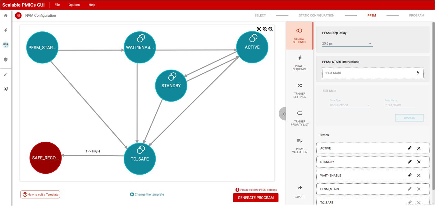
The state diagram which is developed in the PFSM panel includes the user defined mission states and three hardware states, SAFE_RECOVERY, LP_STANDBY, and RUNTIME_BIST. The user defined mission state PFSM_START is required to bridge between the hardware states and the missions states. The TO_SAFE state is required as the transition between mission states and the hardware state SAFE_RECOVERY. As shown in Figure 8-12, the panel focuses on the mission states and the SAFE_RECOVERY, LP_STANDBY, and RUNTIME_BIST hardware states which can be accessed from the mission state via the PFSM.
PFSM_START, TO_SAFE, and SAFE_RECOVERY states are required.
 Figure 8-12 PFSM State Diagram
Panel
Figure 8-12 PFSM State Diagram
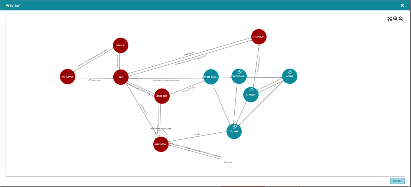
PanelFigure 8-13 shows the complete state machine with the additional transitions associated between the hardware and mission states. The complete state machine can be viewed by selecting the export icon (next to GENERATE PROGRAM) in the lower right corner. Please refer to the device specification for a more detailed description of the states and the transitions.
 Figure 8-13 Complete State Diagram